4.5. Applying Visualization Filters
In this tutorial we will be covering the various types of filters that can be applied to geometries.
There are currently three types of filters:
Clip Filter
Slice Filter
Threshold Filter
Quadric Clustering Filter
Image Resample Filter
A filter can be applied to any geometry or any other filter. The following sections will detail what each of these filters do and how to use them.
Since we are only working with one geometry at a time, for this tutorial
it can be helpful to hide all other geometries by clicking the ![]() icon so that it looks like this
icon so that it looks like this ![]() .
Once you’ve hidden any other geometries make sure the geometry you wish
to filter is selected in the Visualization Pipeline Browser before
continuing with any of the following sections.
.
Once you’ve hidden any other geometries make sure the geometry you wish
to filter is selected in the Visualization Pipeline Browser before
continuing with any of the following sections.
Clip Filter
The Clip Filter is used to cut through a 3D dataset, allowing you to inspect the interior regions. It generates a new dataset by using a plane or box to view a region of interest (ROI) within the original geometry.
Select the geometry or filter item in the tree view you wish to apply the filter to and click the clip button (
 ).
).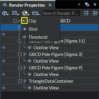
Figure 4.32 Clip Button Location
At this point, you should notice two things happen as a result:
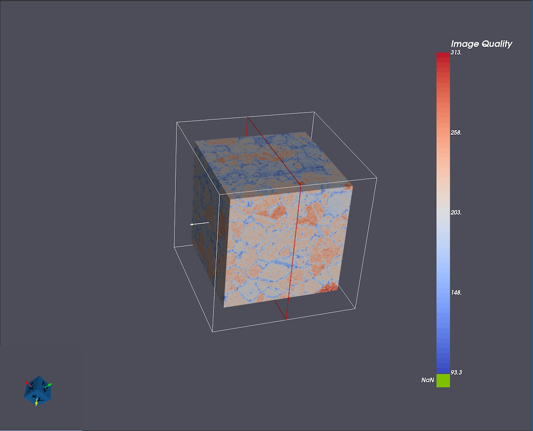
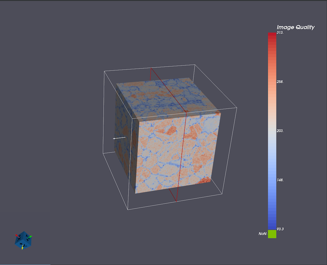
In the Render Window your geometry will be shown with a box surrounding it (1), a red plane showing the clipping plane’s location (2) with respect to the geometry, and an arrow specifying which direction from the clipping plane to keep the geometry (3), this arrow also represents the clipping plane’s normal direction.
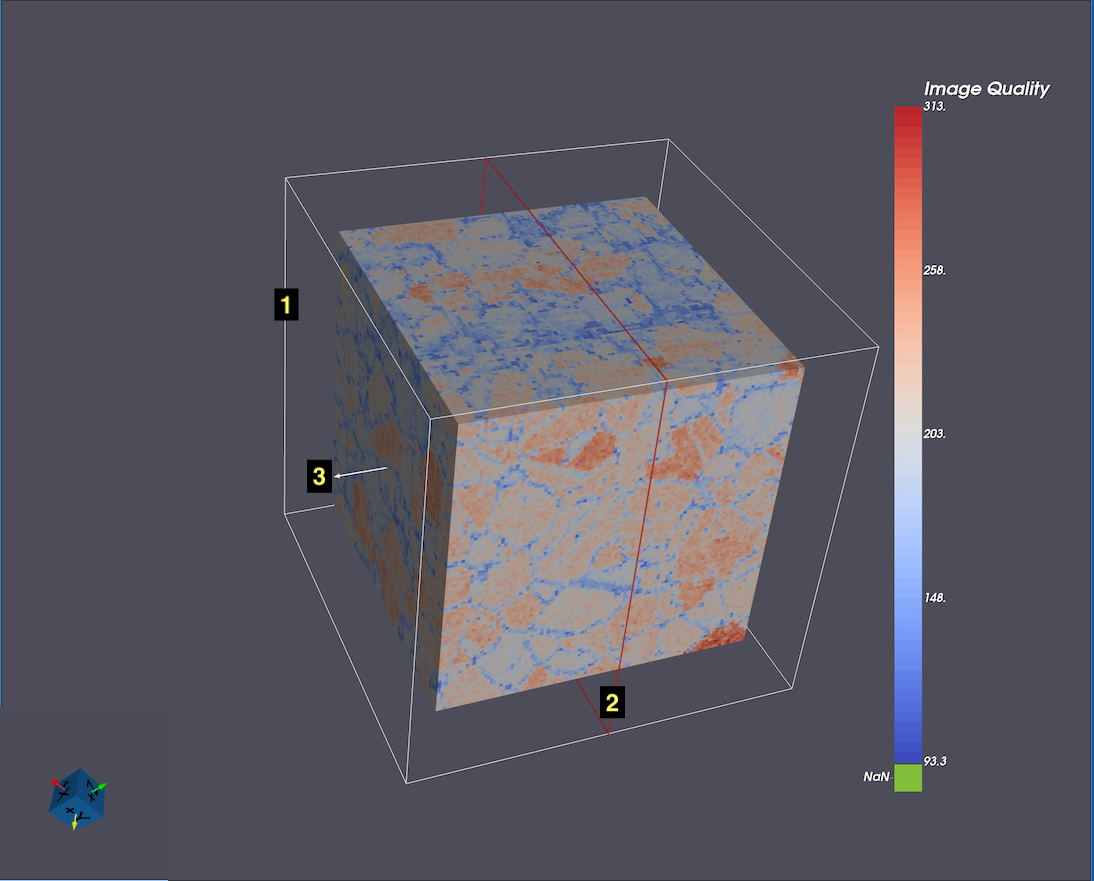
Figure 4.33 Clip Filter Render Window
In the Visualization Properties section of the Render Properties view, you will see all the clipping filter options.
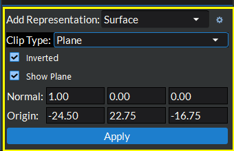
Figure 4.34 Visualization Properties Clip Filter
Choose the clip type by clicking the Clip Type drop down box at the top of the settings area. There are two different options within the Clip Type box:
Clip by plane: user must define a plane where the clipping will take place and which side of the plane the geometry will be removed from
Clip by box: user must define a box where the clipping will take place and whether to keep the geometry inside the box or outside the box
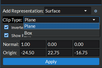
Figure 4.35 Select Clip Type
Choose the “direction” in which the clipping will take place by toggling the Inverted checkbox located below the Clip Type option in the Visualization Properties section. When clipping by plane this will change which side of the plane the geometry will be kept after clipping (the direction the arrow is pointing defines the side of the plane in which geometry is kept). When clipping by box this will define whether the geometry is clipped (removed) inside the box or outside the box (checked = remove geometry outside the box).
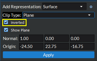
Figure 4.36 SelectClipDirection
Define the clip geometry: This is done via the input sections in the Visualization Properties section or by selecting and editing the clip geometry via the Render Window. These methods are interchangeable/cross-compatible, thus users can switch between these two methods of editing the clip geometry at any point in this step.
NOTE: The clip geometry in the Render Window updates automatically as settings are changed in the Visualization Properties and vise-versa.
Clipping with planes
Defining with the Visualization Properties inputs: Enter the normal vector to the plane and the origin point on the plane in the corresponding input boxes.
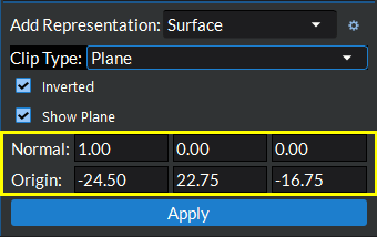
Figure 4.37 Define Clip Plane Geometry
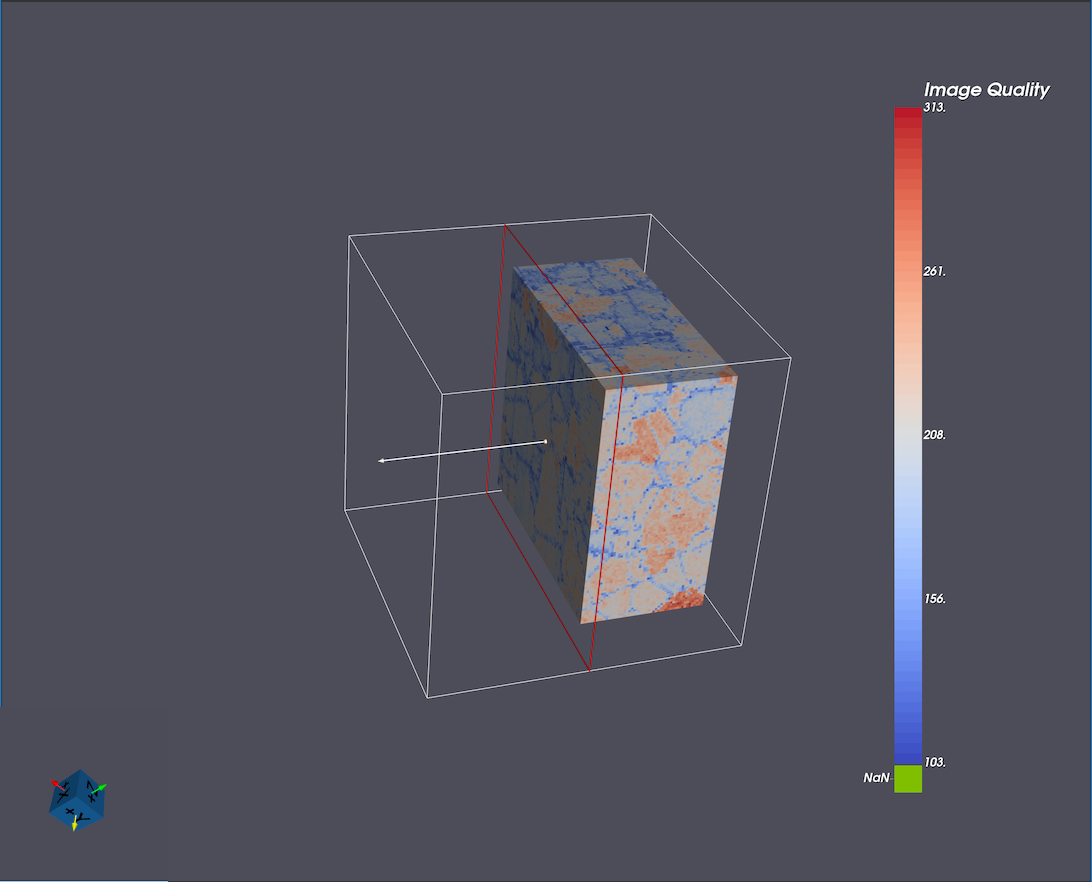
Defining via the Render Window: Click and drag on the red plane geometry (2) in the Render Window to move the plane’s origin to the appropriate spot or click and drag the white arrow (3) to change the plane’s normal direction. [(1) is an unused label in the following image]
Figure 4.38 Clip Filter Render Window
Clipping with boxes
Defining with the Visualization Properties inputs: Enter the translation, rotation, and scale values in the corresponding input boxes.
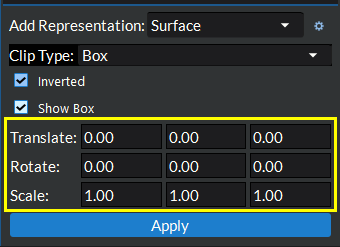
Figure 4.39 Define Clip Box Geometry
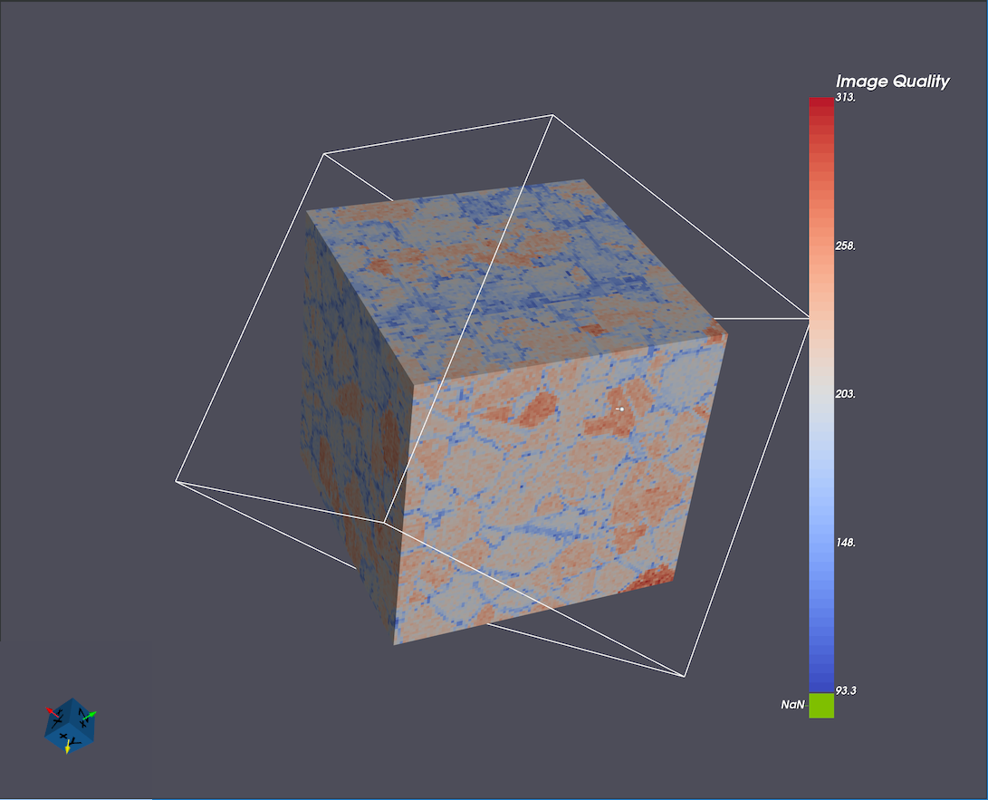
Defining via the Render Window: Click and drag on the white box geometry (1) in the Render Window to change the box’s translation and rotation. or Click and drag and of the three white axes lines (2) to change the box’s x, y, and z scaling.
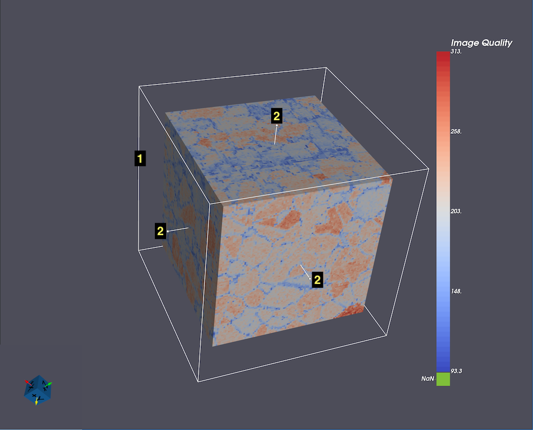
Figure 4.40 Clip Filter Render Window
Click the Apply button to apply the clip filter to your geometry.
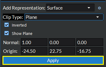
Figure 4.41 Apply Clip Filter
Users may show or hide the clipping geometry at any point in this process by toggling the Show Plane (or Show Box) option just below the Inverted option.
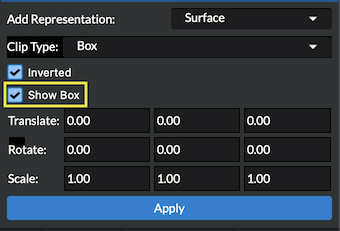
Figure 4.42 Show/Hide Clip Geometry
Plane Original |
Plane Clipped |
|---|---|
|
|
Box Original |
Box Clipped |
|---|---|
|
|
Slice Filter
The Slice Filter will slice the geometry at the specified plane. The user will specify a plane in which only geometry coinciding with this plane will be shown.
Select the geometry or filter item in the tree view you wish to apply the filter to and click the slice button (
 ).
).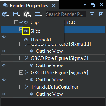
Figure 4.43 Slice Button Location
At this point, you should notice two things happen as a result:
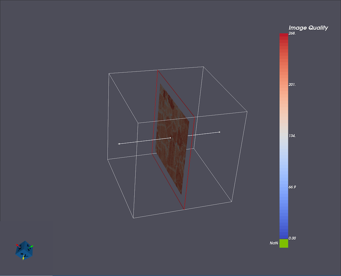
In the Render Window your geometry will be shown with a box surrounding it (1), a red plane showing the clipping plane’s location (2) with respect to the geometry, and an arrow specifying the planes normal direction (3).
Figure 4.44 Slice Filter Render Window
In the Visualization Properties section of the Render Properties view, you will see all the slicing filter options.
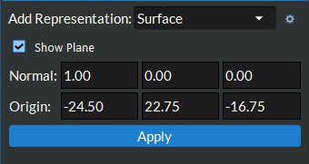
Figure 4.45 Visualization Properties Slice Filter
Define the slice geometry: This is done via the input sections below the Visualization Pipeline Browser section or by selecting and editing the slice geometry via the Render Window. These methods are interchangeable/cross-compatible, thus users can switch between these two methods of editing the slice geometry at any point in this step.
NOTE: The slice geometry in the Render Window updates automatically as settings are changed in the Visualization Properties and vise-versa.
Defining with the inputs: Enter the normal vector to the plane and the origin point of the plane in the corresponding input boxes.
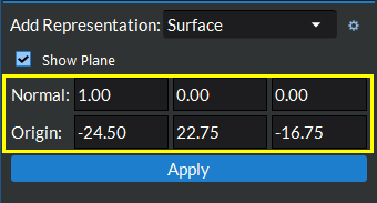
Figure 4.46 Define Slice Plane Geometry
Defining via the Render Window: Click and drag on the red plane geometry (2) in the Render Window to move the plane’s origin to the appropriate spot or click and drag the white arrow (3) to change the plane’s normal direction. [(1) is an unused label in the following image]
Figure 4.47 Slice Filter Render Window
Click the Apply button to apply the slice filter to your geometry.
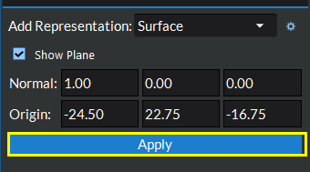
Figure 4.48 Apply Slice Filter
Users may show or hide the slicing geometry at any point in this process by toggling the Show Plane option at the top of the Visualization Properties section.
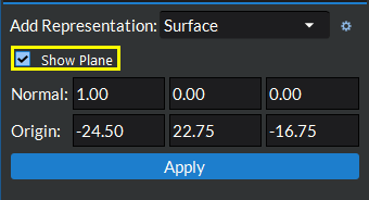
Figure 4.49 Show/Hide Slice Geometry
Original |
Sliced |
|---|---|
|
|
Threshold Filter
The Threshold Filter will remove any geometry/data that does not fall within the specified range for the selected data set.
Select the geometry or filter item in the tree view you wish to apply the filter to and select the threshold button (
 ).
).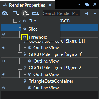
Figure 4.50 Threshold Filter Menu Item
Select the data set on which to define the threshold via the Scalars drop down box.
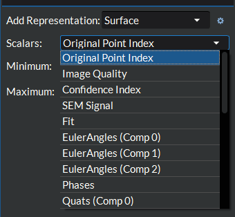
Figure 4.51 Select Threshold DataSet
Define the threshold minimum and maximum values. You may do this one of two ways;
Enter the respective values in the provided input boxes along the right-hand side:
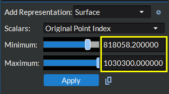
Figure 4.52 Define Threshold Range Input Boxes
Move the blue slider bar handles to the spot that represents the minimum/maximum values you want. The values in the input boxes to the right of the slider bars will update to match the value represented by the slider bar as you edit.
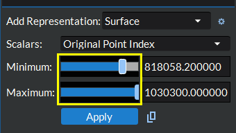
Figure 4.53 Define Threshold Range Sliders
Click the Apply button at the bottom to apply the threshold to your geometry.
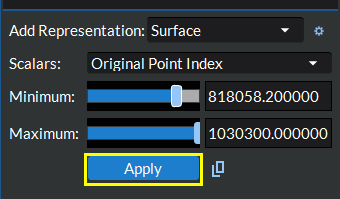
Figure 4.54 Apply Threshold Criteria
Original |
Thresholded |
|---|---|
|
|

Optional : Create a DREAM3D-NX Multi-Threshold Objects Filter from the values in this visualization threshold filter(and any anscestor or descendant visualization threshold filters linked to this one if desired). The new Multi-Threshold Objects filter will be appended to the end of the current pipeline. This feature is designed to be used with the pipeline from which the array/geometry originally came. If there is no pipeline currently loaded or the array(s) cannot be found in the data structure of the last enabled filter, then no Multi-Threshold Objects filter will be added.
Figure 4.55 Create Multi-Threshold Objects Filter from Visualization Threshold Filter
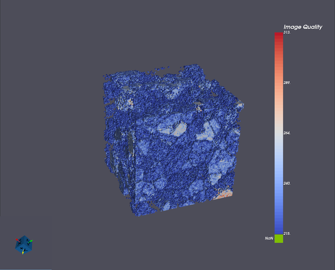
Quadric Clustering Filter
Quadric clustering is a mesh simplification technique that reduces the number of triangles in a 3D surface while preserving its overall shape. The algorithm divides space into a regular 3D grid and groups together vertices that fall within the same grid cell. Each group of vertices is replaced by a single new vertex whose position is chosen to minimize geometric error using quadric error metrics, which measure how much the surface would be distorted. The mesh is then rebuilt using these new vertices, removing redundant or degenerate triangles. Quadric clustering is fast, scales well to large datasets, and is well suited for generating simplified representations of complex geometries in DREAM3D-NX, such as for level-of-detail generation or efficient visualization.
Select the geometry or filter item in the tree view you wish to apply the filter to and select the quadric clustering button (
 ).
).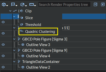
Figure 4.56 Quadric Clustering Filter Menu Item
Select the new dimensions. This will specify the number of bins along the x, y, and z axes of the reduced dataset.
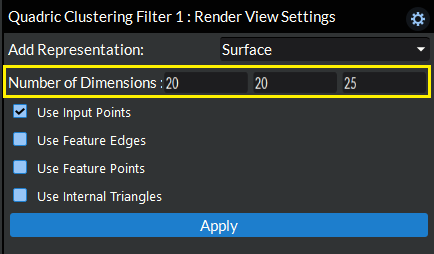
Figure 4.57 Select Dimensions
Select whether or not to use internal triangles. If checked, triangles completely contained in a spatial bin will be included in the computation of the bin’s quadrics. If not checked, the filters operates faster but the resulting surface may not be as well-behaved
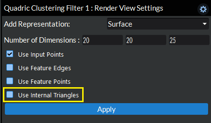
Figure 4.58 Select Use Internal Triangles
Click the Apply button at the bottom to apply the quadric clustering algorithm to your geometry.
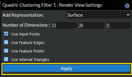
Figure 4.59 Apply Quadric Clustering Criteria
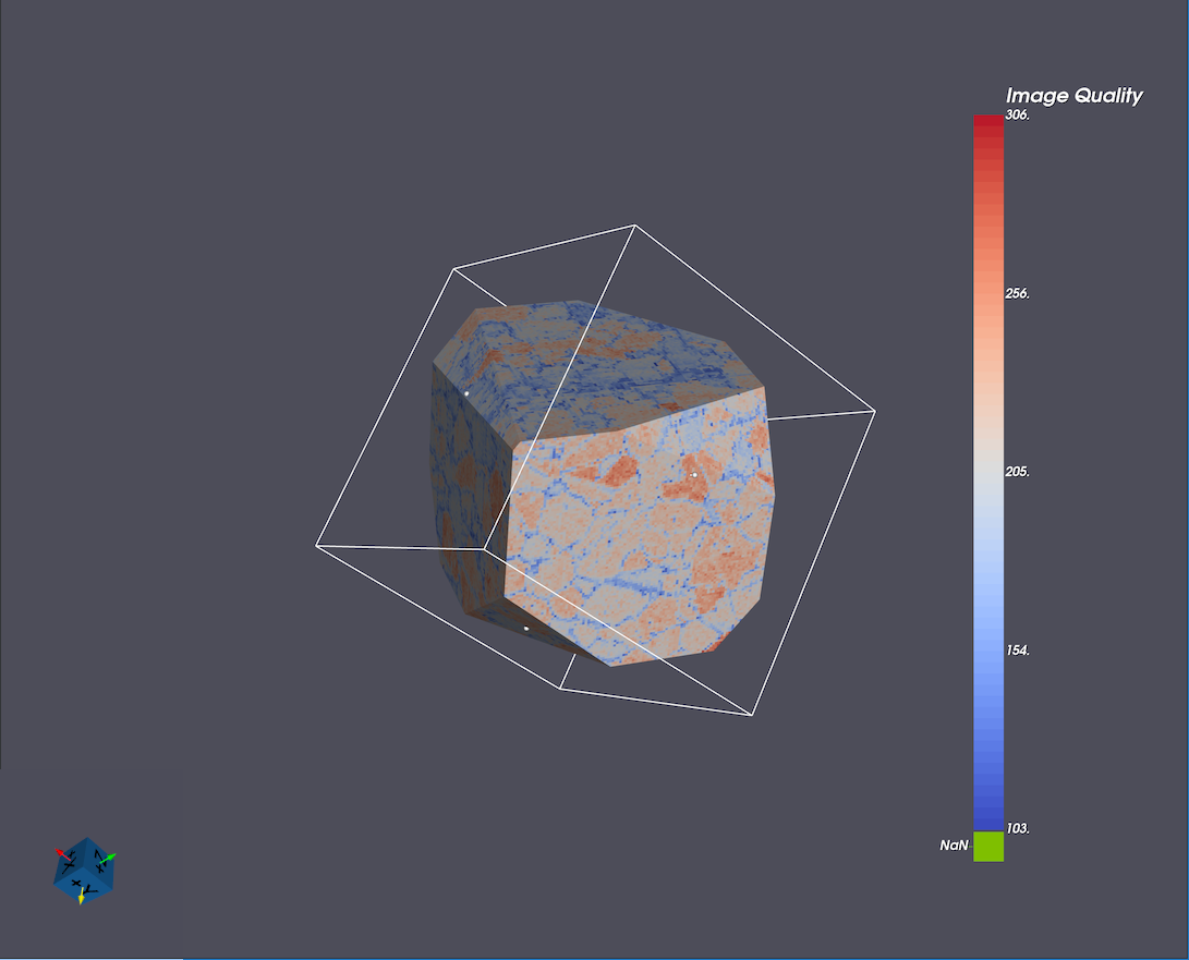
Original |
Decimated |
|---|---|
|
|
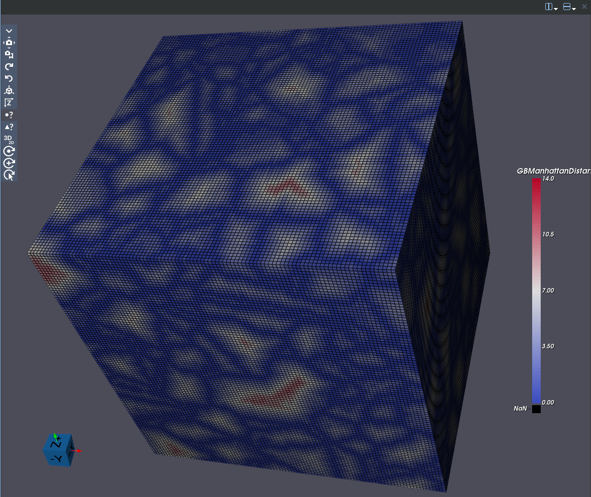
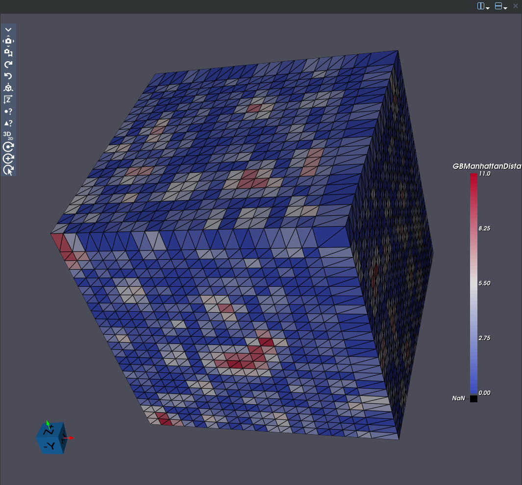
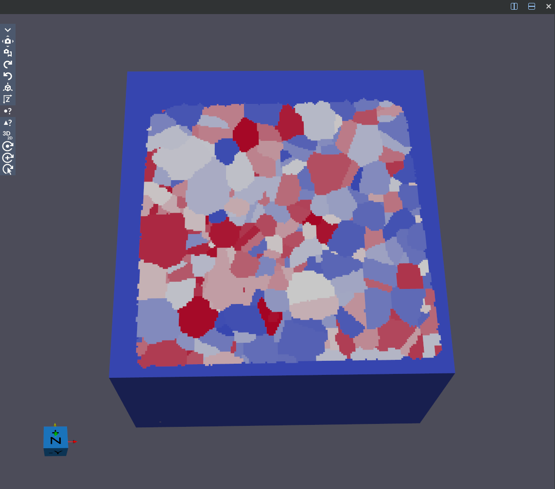
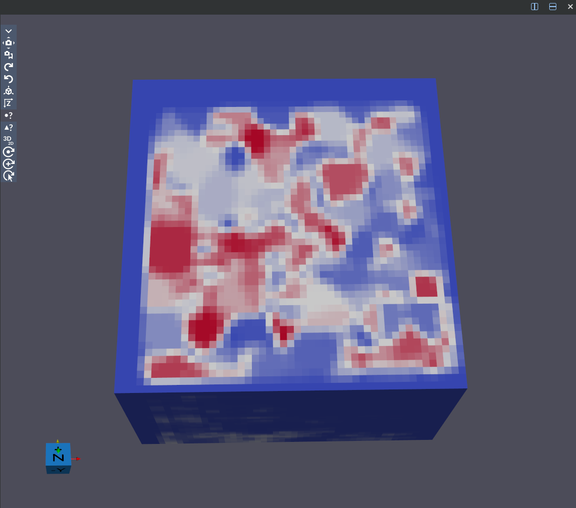
Image Resample Filter
The Image Resample Filter will resample the geometry using the specified dimensions.
Select the geometry or filter item in the tree view you wish to apply the filter to and click the Image Resample button.
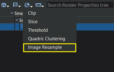
Figure 4.60 Image Resample Button Location
In the Visualization Properties section of the Render Properties view, you will see all the Image Resample filter options.
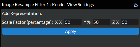
Figure 4.61 Image Resample Filter Properties
Define the scale fators: This is done via the three input boxes in the visualization properties section shown in step 2 above. These values should be a percentage of the original geometry x, y, and z dimensions and will define how much to resample the data set by.
Click the Apply button to apply the image resample filter to your geometry.
Original |
Resampled |
|---|---|
|
|