7.3. Navigating the Views
In this section we describe how to interact with each of the four windows in the Quad View module.
Once a geometry has been loaded into the Quad View, each of the four windows provides a different set of interaction controls appropriate for its view type.
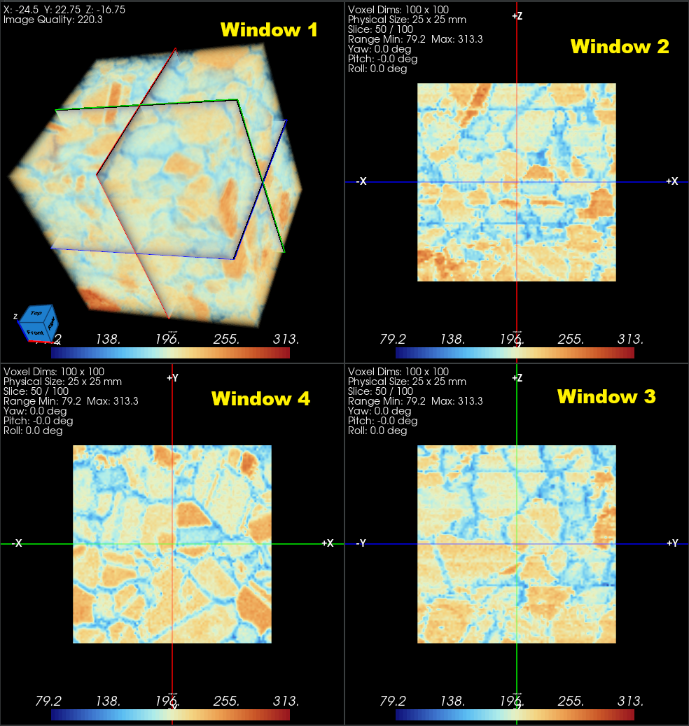
Figure 7.15 Overview of the Four Windows With Data Loaded
Window 1 — 3D Volume Rendering
Window 1 (top-left) displays a 3D volume rendering of the entire dataset. The three orthogonal slice planes from Windows 2–4 are drawn as colored overlays inside the volume so their current positions are always visible in context.
Mouse Interactions
Action |
Result |
|---|---|
Left-click + drag |
Rotate the camera around the dataset |
Middle-click + drag |
Pan the camera |
Right-click + drag or scroll wheel |
Zoom in / out |
The orientation widget (view cube) displayed in the corner of Window 1 shows the current camera orientation. Clicking a face, edge, or corner of the view cube snaps the camera to the corresponding standard orientation (e.g. clicking the +X face looks down the X axis). The view cube updates continuously as the camera is rotated.
The face labels can be customized application-wide via the Orientation Marker Preferences entry on the Application Preferences page (Default / XYZ / Custom presets). Changes apply immediately to every open Quad View pane.
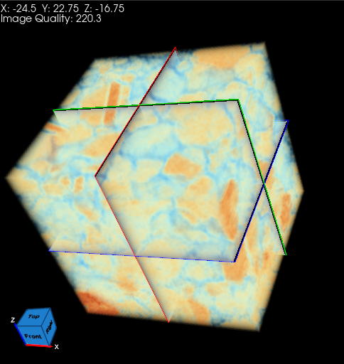
Figure 7.16 Volume Rendering in Window 1 With the Orientation Widget Visible
Note
Interaction with the slice planes is disabled in Window 1. To reposition the planes, use the axis lines in Windows 2–4.
Volume Keyboard Shortcuts
Key |
Result |
|---|---|
R |
Reset the camera to its default position |
X |
View along the X axis |
Y |
View along the Y axis |
Z |
View along the Z axis |
Windows 2-4 — Orthogonal Slice Planes
Windows 2, 3, and 4 each display one orthogonal 2D slice of the geometry:
Window 2 (top-right): XZ plane — the horizontal axis is X, the vertical axis is Z.
Window 3 (bottom-right): YZ plane — the horizontal axis is Y, the vertical axis is Z.
Window 4 (bottom-left): XY plane — the horizontal axis is X, the vertical axis is Y.
Each window shows two crosshair axis lines — one horizontal and one vertical. These lines represent the intersection of the other two slice planes with the current view plane. Directional axis labels (e.g. +X, -X, +Z, -Z) track along their respective axis line to the nearest viewport border, updating in real time as the slice planes are moved or rotated. Each label identifies the axis name and the positive or negative direction at that border. The colors of the axis lines and plane overlays match the corresponding axis colors in the orientation widget (X = red, Y = green, Z = blue).
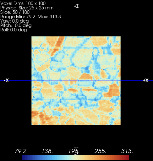
Figure 7.17 Window 2 Showing the XZ Slice Plane With Axis Labels and Crosshair Lines
Changing the Slice Position
To move a slice plane (change the slice number for that axis), click and drag anywhere along the axis line corresponding to that plane:
Clicking and dragging a horizontal axis line moves the horizontal plane (the plane perpendicular to the vertical axis of the current window). The slice in the window whose plane runs horizontal will update.
Clicking and dragging a vertical axis line moves the vertical plane. The slice in the window whose plane runs vertical will update.
Clicking and dragging the intersection point (where the two axis lines cross) moves both planes simultaneously.
All four windows update in real time as the slice position changes, including the plane positions shown in the 3D volume rendering in Window 1.
Scrolling Through Slices
When the mouse cursor is positioned over Windows 2–4, the scroll wheel steps through slices along the axis perpendicular to the current view:
Scrolling up advances to the next slice.
Scrolling down goes back to the previous slice.
Panning and Zooming
The following mouse interactions are available in Windows 2–4:
Right-click + drag: Zooms the view in and out. When Thick Slab mode is enabled, right-click + drag adjusts the slab thickness instead of zooming.
Middle-click + drag: Pans the view without changing the slice position.
The zoom and pan state in each window is independent. To reset all views back to the full extent of the data, click the Reset Planes button in the Controls Panel — this restores each window’s camera and all three slice planes to their default positions simultaneously.
Oblique Mode Interactions
When Oblique Reslice mode is enabled (via the Controls Panel checkbox), additional rotation controls appear in Windows 2–4:
Action |
Result |
|---|---|
Hover over a crosshair axis line |
Black (white-outlined) triangle rotation arrows appear on the line |
Left-click + drag on a rotation arrow (left/right of vertical line) |
Rotate the slice plane around the vertical axis |
Left-click + drag on a rotation arrow (above/below horizontal line) |
Rotate the slice plane around the horizontal axis |
Note
When oblique reslice is enabled, the Yaw, Pitch, and Roll values in the annotation overlay update to reflect the current orientation angles of each slice plane. See Oblique Reslicing for full details.
Slice View Keyboard Shortcuts
Key |
Result |
|---|---|
O |
Reset the reslice cursor to its default (centered) position |
R |
Reset window/level to initial values; reset camera when Shift or Ctrl is held |
X |
Switch to X-axis view orientation |
Y |
Switch to Y-axis view orientation |
Z |
Switch to Z-axis view orientation |