4.7. Per-Geometry Default Data View
In this section we explain how to configure the default 3D data view (representation) that is automatically applied to each geometry type when data is imported into the visualization.
Overview
When a pipeline runs or a file is loaded, DREAM3D-NX automatically creates an initial data view for each geometry. The Per-Geometry Default Data View feature lets you choose a different starting representation for each of the six supported geometry types independently, so the visualization is immediately useful without requiring manual adjustments after every pipeline run.
Every geometry type always receives at least an Outline representation. Outline is the built-in minimum — it is used whenever no other default has been configured, and for any geometry type that is not yet listed in the Preferences dialog.
The six configurable geometry types are:
Image Geometry — regular voxel grid (e.g. from an SEM or CT scan)
Rectilinear Grid Geometry — non-uniform voxel grid with variable spacing
Vertex Geometry — unconnected point cloud
Edge Geometry — connected line segments
Triangle Geometry — triangulated surface mesh
Quad Geometry — quadrilateral surface mesh
Configuring the Per-Geometry Defaults
Per-geometry defaults are configured in the Visualization tab of the DREAM3D-NX Preferences dialog.
Open Preferences from the application menu (DREAM3D-NX → Preferences on macOS, Edit → Preferences on Windows/Linux).
Select the Visualization tab.
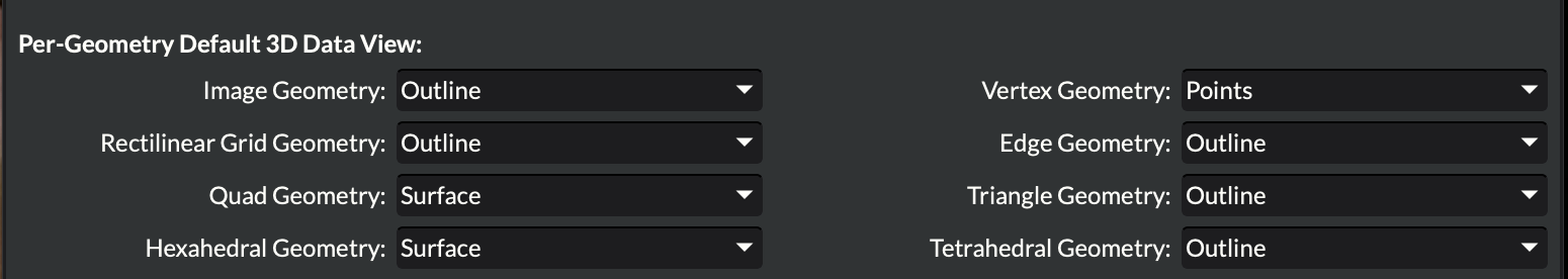
Figure 4.62 The Visualization tab of the Preferences dialog with per-geometry default data view settings for each geometry type.
Locate the Per-Geometry Default 3D Data View section.
For each geometry type, use the corresponding drop-down list to select the desired default representation. The available options are:
Representation
Description
Outline
Bounding-box wireframe — lightweight, shows overall extent
Points
Renders every vertex as a point
Wireframe
Renders all cell edges
Surface
Filled surface rendering
Volume
Direct volume rendering (Image/Rectilinear Grid only)
2D Image/Slice
Slice plane view (Image/Rectilinear Grid only)
Click OK (or Apply) to save your changes. The new defaults take effect immediately for any geometry imported after the dialog is closed.
Note
Changing the per-geometry defaults does not alter data views that are already present in the Visualization Pipeline Browser. Only newly imported data sources are affected.
Recommended Defaults by Geometry Type
The following defaults are a useful starting point for common workflows:
Geometry Type |
Suggested Default |
Rationale |
|---|---|---|
Image Geometry |
Surface or 2D Image/Slice |
Most image-data workflows benefit from an immediate surface or slice view |
Rectilinear Grid Geometry |
Surface or Outline |
Surface shows the outer extent; use Outline for very large grids |
Vertex Geometry |
Points |
Point clouds are most naturally viewed as points |
Edge Geometry |
Wireframe |
Line/edge data is best viewed as connected edges |
Triangle Geometry |
Surface |
Triangle meshes are typically rendered as filled surfaces |
Quad Geometry |
Surface |
Quad meshes are typically rendered as filled surfaces |
Persistence
All per-geometry default selections are stored in the application’s
QSettings store under the VisualizationSettings group. They persist
between DREAM3D-NX sessions and are restored automatically on start-up.
The factory default for every geometry type is Outline.
See also
Creating Data Views — detailed descriptions of every representation type and its configurable options.
Importing Data — how geometry data is loaded into the Visualization Toolkit from pipelines and files.