10.81. Read Images [3D Stack] (ITK)
This filter directly wraps an ITK filter of the same name.
Group (Subgroup)
ITKImageProcessing (ITKImageProcessing)
Description
Read in a stack of 2D images and stack the images into a 3D Volume using the ITK library. Supports most common scalar pixel types and the many file formats supported by ITK.
Processing Order
Image operations are applied in the following order:
Read image
Crop image
Resample image
Convert to grayscale
Flip image in X or Y
Origin & Spacing Caveats
The filter will create a new Image Geometry. The user can optionally override the origin and spacing for the created geometry. The default values from the input files will be used unless the user explicitly enables the “Set Origin” and/or “Set Spacing” options. If the user needs to have the created Image Geometry located in a different location in the global reference frame, the user can change the default origin value. The “origin” of the image is at a normal Cartesian style origin.
When setting a custom origin, the user can choose whether to place the origin at the corner of the geometry (default) or at the center of the geometry.
The Origin & Spacing Processing Order parameter controls when origin and spacing overrides are applied relative to the Processing Order above:
Preprocessed: Origin and spacing are applied before the image cropping step, so the order becomes:
Read image
Set origin and spacing values
Crop image
Resample image
Convert to grayscale
Flip image in X or Y
Postprocessed: Origin and spacing are applied after the image flipping step, so the order becomes:
Read image
Crop image
Resample image
Convert to grayscale
Flip image in X or Y
Set origin and spacing values
Resampling Caveats
The user can decide to scale the images as they are being read in by turning on the Scale Images option, and setting a scale value. A scale value of 10.0 resamples the images in the stack to one-tenth the number of pixels, a scale value of 200.0 resamples the images in the stack to double the number of pixels. The default scale value is 100.0.
Data Type Conversion
The user can optionally convert the image data to a different data type by enabling the “Set Image Data Type” option. Supported output data types include:
uint8
uint16
uint32
Cropping Caveats
The user can crop the incoming image geometry using the Cropping Options section. The cropping type options are:
No Cropping: Read the full volume into an image geometry
Voxel Subvolume: Read a subvolume into an image geometry using voxel coordinates
Physical Subvolume: Read a subvolume into an image geometry using physical coordinates
Both subvolume cropping types have checkboxes to turn on/off cropping in each of the X, Y, and Z dimensions. For example, if Physical Subvolume is selected, Crop Y Dimension is enabled, and Crop X Dimension and Crop Z Dimension are disabled, then the incoming volume will be cropped in the Y dimension only and the cropping bounds will be in physical units.
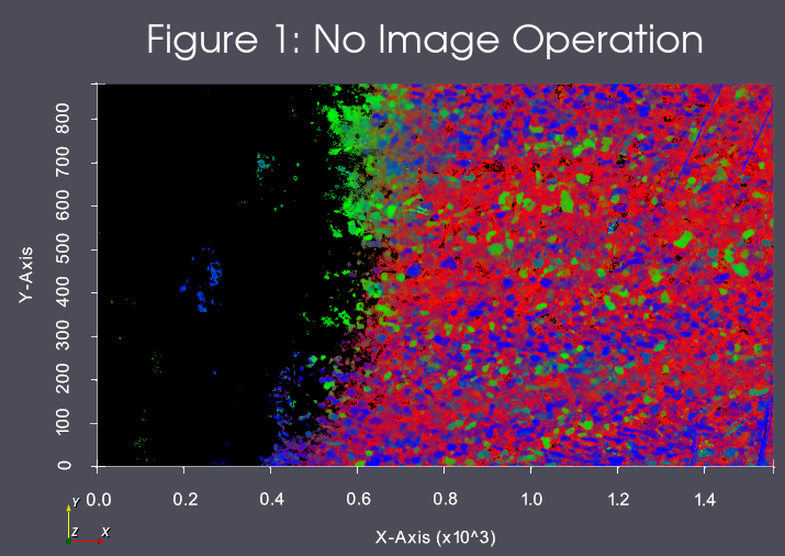
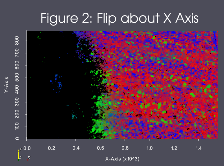
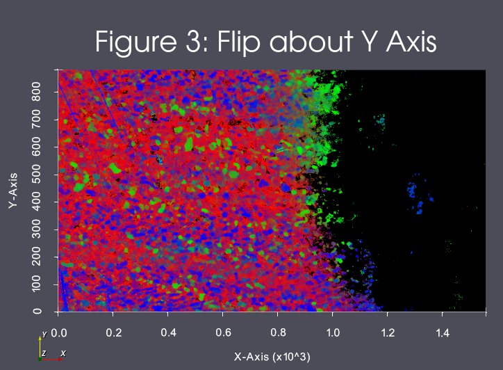
Image Operations
The user can select to flip the images about the X or Y Axis during import. The result of these operations can be seen in Figures 1, 2 and 3
Input Parameter(s)
Parameter Name |
Parameter Type |
Parameter Notes |
Description |
|---|---|---|---|
Input File List |
GeneratedFileList |
The list of 2D image files to be read in to a 3D volume |
Cropping Options
Parameter Name |
Parameter Type |
Parameter Notes |
Description |
|---|---|---|---|
Cropping Options |
CropGeometry |
The cropping options used to crop images. These include picking the cropping type, the cropping dimensions, and the cropping ranges for each chosen dimension. |
Origin & Spacing Options
Parameter Name |
Parameter Type |
Parameter Notes |
Description |
|---|---|---|---|
Set Origin |
Bool |
Specifies if the origin should be changed |
|
Origin |
Vector of Float64 Values |
Order=X,y,Z |
The origin of the 3D volume |
Set Spacing |
Bool |
Specifies if the spacing should be changed |
|
Spacing |
Vector of Float64 Values |
Order=X,y,Z |
The spacing of the 3D volume |
Origin & Spacing Processing |
Choices |
Whether the origin & spacing should be preprocessed or postprocessed. |
Resampling Options
Parameter Name |
Parameter Type |
Parameter Notes |
Description |
|---|---|---|---|
Resample Images |
Choices |
Mode can be [0] Do Not Rescale, [1] Scaling as Percent, [2] Exact X/Y Dimensions For Resampling Along Z Axis |
|
Scaling (%) |
Scalar Value |
Float32 |
The scaling of the 3D volume, in percentages. Percentage must be greater than or equal to 1.0f. Larger percentages will cause more voxels, smaller percentages will cause less voxels. For example, 10.0 is one-tenth the original number of pixels. 200.0 is double the number of pixels. |
Exact 2D Dimensions (Pixels) |
Vector of UInt64 Values |
Order=X,Y |
The supplied dimensions will be used to determine the resampled output geometry size. See associated Filter documentation for further detail. |
Other Slice Options
Parameter Name |
Parameter Type |
Parameter Notes |
Description |
|---|---|---|---|
Convert To GrayScale |
Bool |
The filter will show an error if the images are already in grayscale format |
|
Color Weighting |
Vector of Float32 Values |
Order=Red,Green,Blue |
RGB weights for the grayscale conversion using the luminosity algorithm. |
Flip Slice |
Choices |
Operation that is performed on each slice. 0=None, 1=Flip about X, 2=Flip about Y |
|
Set Image Data Type |
Bool |
Set the final created image data type. |
|
Output Data Type |
Choices |
Numeric Type of data to create |
Output Data
Parameter Name |
Parameter Type |
Parameter Notes |
Description |
|---|---|---|---|
Created Image Geometry |
DataGroupCreation |
The path to the created Image Geometry |
|
Cell Data Name |
DataObjectName |
The name of the created cell attribute matrix |
|
Created Image Data |
DataObjectName |
The path to the created image data array |
Note on Resampling
The optional resampling parameter has two options that affect the output image and size of the resulting geometry.
Scaling Factor (1) - This is the scaling option that previously existed with the filter. It functions by providing a float value that becomes a XYZ scaling factor vector that is applied to each image before it is inserted into the final geometry. This means that the number of pixels in the resulting output image will be resampled to
{X * (ScalingFactor / 100.0), Y * (ScalingFactor / 100.0), Number of Images In Stack} (XYZ). This means that a value of 100 (Like 100%) will NOT perform any resampling. A value of 50 will produce a final output image that has half as many pixels along the X and Y Axis. A value of 200 will have twice as many voxels along the X and Y Axis.Exact XY Dimensions (2) - This is provided to allow for precision resampling along the Z Axis. The number of pixels in the resulting output image will be resampled to
{User Supplied X, User Supplied Y, Number of Images In Stack} (XYZ).
Both options are different ways to parameterize the resampling functionality. The main difference should be that Scaling Factor (1) is implicity uniform in its resampling across the X and Y dimensions, but the same is not true for Exact XY Dimensions (2).
Example Pipelines
(08) Image Initial Visualization
(09) Image Segmentation
License & Copyright
Please see the description file distributed with this plugin.
DREAM3D-NX Help
If you need help, need to file a bug report or want to request a new feature, please head over to the DREAM3DNX-Issues GitHub site where the community of DREAM3D-NX users can help answer your questions.