10.69. Create Geometry (Image)
Group (Subgroup)
Core (Generation)
⚠ Deprecation Notice. This filter is deprecated. Use the more general Create Geometry filter instead. This filter is retained for compatibility with legacy pipelines.
Description
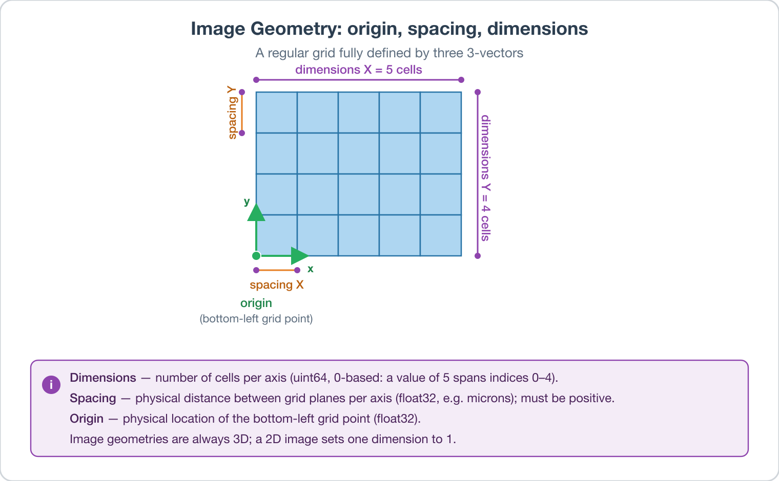
This Filter creates an Image Geometry – a regular grid of voxels (3D) or pixels (2D). The user supplies the dimensions, spacing, and origin; the filter creates a new geometry object with no cell data attached. Use it before reading raw binary data into a grid, before creating synthetic data on a regular grid, or whenever you need a fresh empty Image Geometry.
An Image Geometry is the simplest and most widely used DREAM3D-NX geometry type. For dimensionality d, only 3 × d numbers are needed to completely define it: three d-vectors for the dimensions, origin, and spacing.
Dimensions – grid extents. Stored as unsigned 64-bit integers. Dimensions are 0-based, so a dimension of 10 spans extents 0-9. No dimension may be zero or negative.
Spacing – physical distance between grid planes along each axis. Stored as 32-bit floats. Units match the source data (e.g., microns per voxel). Spacing must be positive and non-zero. (Resolution was the older name; spacing is preferred because resolution is ambiguous.)
Origin – physical location of the bottom-left grid point in the geometry’s coordinate system. Stored as 32-bit floats. No value restriction.
All Image Geometries are stored as 3D; a 2D image is represented by setting one dimension to exactly 1, producing a plane. Downstream filters that care about dimensionality (e.g., Compute Feature Shapes) detect the 2D case automatically.
Since all Image Geometries are implicitly 3D, the building block is a voxel, which is a 3D object. The basic Element type for an Image Geometry is Cell. Attribute arrays associated with cells are stored in x-y-z raster order (fastest to slowest).
Example Usage
When importing raw binary data on a regular grid, run this filter first to create the geometry description; then attach data via subsequent reader filters.
Required Input Sources
None. The geometry is created from user-supplied parameters.
Input Parameter(s)
Parameter Name |
Parameter Type |
Parameter Notes |
Description |
|---|---|---|---|
Output Geometry Name |
DataGroupCreation |
The complete path to the Geometry being created |
|
Dimensions |
Vector of UInt64 Values |
Order=X,Y,Z |
The number of cells in each of the X, Y, Z directions |
Origin |
Vector of Float32 Values |
Order=X,Y,Z |
The origin of each of the axes in X, Y, Z order |
Spacing |
Vector of Float32 Values |
Order=X,Y,Z |
The length scale of each voxel/pixel |
Cell Data Name |
DataObjectName |
The name of the cell Attribute Matrix to be created |
Example Pipelines
License & Copyright
Please see the description file distributed with this Plugin
DREAM3D-NX Help
If you need help, need to file a bug report or want to request a new feature, please head over to the DREAM3DNX-Issues GitHub site where the community of DREAM3D-NX users can help answer your questions.