9.132. Rotate Sample Reference Frame
Group (Subgroup)
Sampling (Rotating/Transforming)
Description
NOTE: As of July 2023, this filter is only verified to work with a rotation angle of 90 or 180 degrees, a rotation axis of (010) || (100) || (001) The origin must also be (0, 0, 0).
This Filter will rotate the spatial reference frame around a user defined axis, by a user defined angle. The Filter will modify the (X, Y, Z) positions of each Cell to correctly represent where the Cell sits in the newly defined reference frame. For example, if a user selected a rotation angle of 90o and a rotation axis of (001), then a Cell sitting at (10, 0, 0) would be transformed to (0, -10, 0), since the new reference frame would have x’=y and y’=-x.
The equivalent rotation matrix for the above rotation would be the following:
0 |
-1 |
0 |
1 |
0 |
0 |
0 |
0 |
1 |
Example
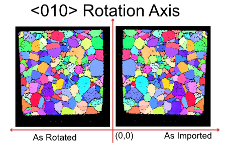
When importing EBSD data from EDAX typically the user will need to rotate the sample reference frame about the <010> (Y) axis. This results in the image comparison below. Note that in the original image the origin of the data is at (0, 0) microns but after rotation the origin now becomes (-189, 0) microns. If you need to reset the origin back to (0,0) then the filter “Set Origin & Spacing” can be run.
Notes
The transformation will most likely create an origin that is different from the input geometry’s origin. If you wish to still keep the input geometry’s origin then there is an option to allow you to do that. By default, the option is OFF so that the origin generated from the transformation is used.
Input Parameter(s)
Parameter Name |
Parameter Type |
Parameter Notes |
Description |
|---|---|---|---|
Perform Slice By Slice Transform |
Bool |
This option is specific to EBSD Data and is not generally used. |
|
Rotation Representation |
Choices |
Which form used to represent rotation (axis angle or rotation matrix) |
|
Rotation Axis-Angle [ |
Vector of Float32 Values |
Order=i,j,k,w (Deg) |
Axis-Angle in sample reference frame to rotate about. |
Perform In-Place Rotation |
Bool |
Performs the rotation in-place for the given Image Geometry |
|
Keep Input Geometry’s Origin |
Bool |
The input geometry’s origin is kept instead of the origin resulting from the transform |
|
Transformation Matrix |
DynamicTable |
The 4x4 Transformation Matrix |
Input Image Geometry
Parameter Name |
Parameter Type |
Parameter Notes |
Description |
|---|---|---|---|
Selected Image Geometry |
Geometry Selection |
Image |
The target geometry on which to perform the rotation |
Output Geometry and Data
Parameter Name |
Parameter Type |
Parameter Notes |
Description |
|---|---|---|---|
Created Image Geometry |
DataGroupCreation |
The location of the rotated geometry |
Example Pipelines
INL Export
Export Small IN100 ODF Data (StatsGenerator)
TxCopper_Exposed
TxCopper_Unexposed
Edax IPF Colors
Confidence Index Histogram
License & Copyright
Please see the description file distributed with this Plugin
DREAM3D-NX Help
If you need help, need to file a bug report or want to request a new feature, please head over to the DREAM3DNX-Issues GitHub site where the community of DREAM3D-NX users can help answer your questions.