9.133. Sample Triangle Geometry on Regular Grid
Group (Subgroup)
Sampling (Resolution)
Description
This Filter “samples” a triangulated surface mesh onto a regular grid (Image Geometry) using scanline rasterization. The user can either create a new Image Geometry by specifying dimensions, spacing, and origin, or use an existing Image Geometry. The filter assigns a Feature Id (or part number) to each voxel based on which region of the surface mesh the voxel falls within.
Algorithm
The sampling is performed using the following scanline rasterization approach:
For each Z-slice of the grid, determine which Triangles intersect the Z-plane at the voxel center height and compute 2D edge segments from those intersections
For each Y-scanline within a Z-slice, find the X-coordinates where the scanline crosses the 2D edges
Sort the crossings by X-coordinate and walk left to right across the voxels, toggling the current Feature Id at each boundary crossing
Assign the current Feature Id to each voxel in the Feature Ids output array
Face Labels / Part Numbers
The Face Labels/Part Numbers input array specifies which Features (or parts) border each Triangle face. This array accepts any integer data type and supports two formats:
2-component arrays: Each face has two labels identifying the Features on either side. When a scanline crosses a face boundary, the algorithm toggles between the two labels. This is the standard format produced by surface meshing filters.
1-component arrays: Each face has a single part number. When a scanline crosses a face boundary, the voxel is assigned the part number of that face. This format is useful for imported meshes (e.g., STL files) where each face belongs to a single part.
The output Feature Ids array will have the same integer data type as the input Face Labels/Part Numbers array.
Origin, Dimension, and Spacing’s Effect on the Output
Subsequent images in this section will always have the correct example on the left. The images below were created by thresholding the Feature Ids to 1.
Origin
Take a moment to consider the following image:
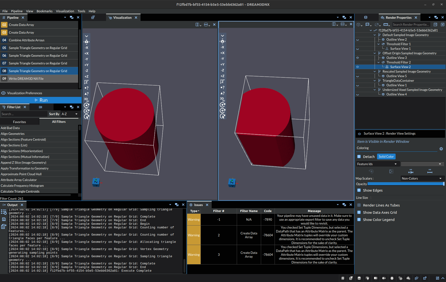
In the above picture, the cylinder on the left is a correct output for a specific .stl model, the origin used was (-1, -1, -1). On the right, there is a cylinder that had the origin set to (3, 2, -1). The change of origin caused a truncating of the geometry, the white outline is roughly the bounding box for the objects. Thus, when you are defining the origin it is important to consider how the resulting box will intersect the geometry. For most cases, it is recommended to ensure the origin of the box falls below that of the Geometry to avoid truncation.
Dimension
Take a moment to consider the following image:
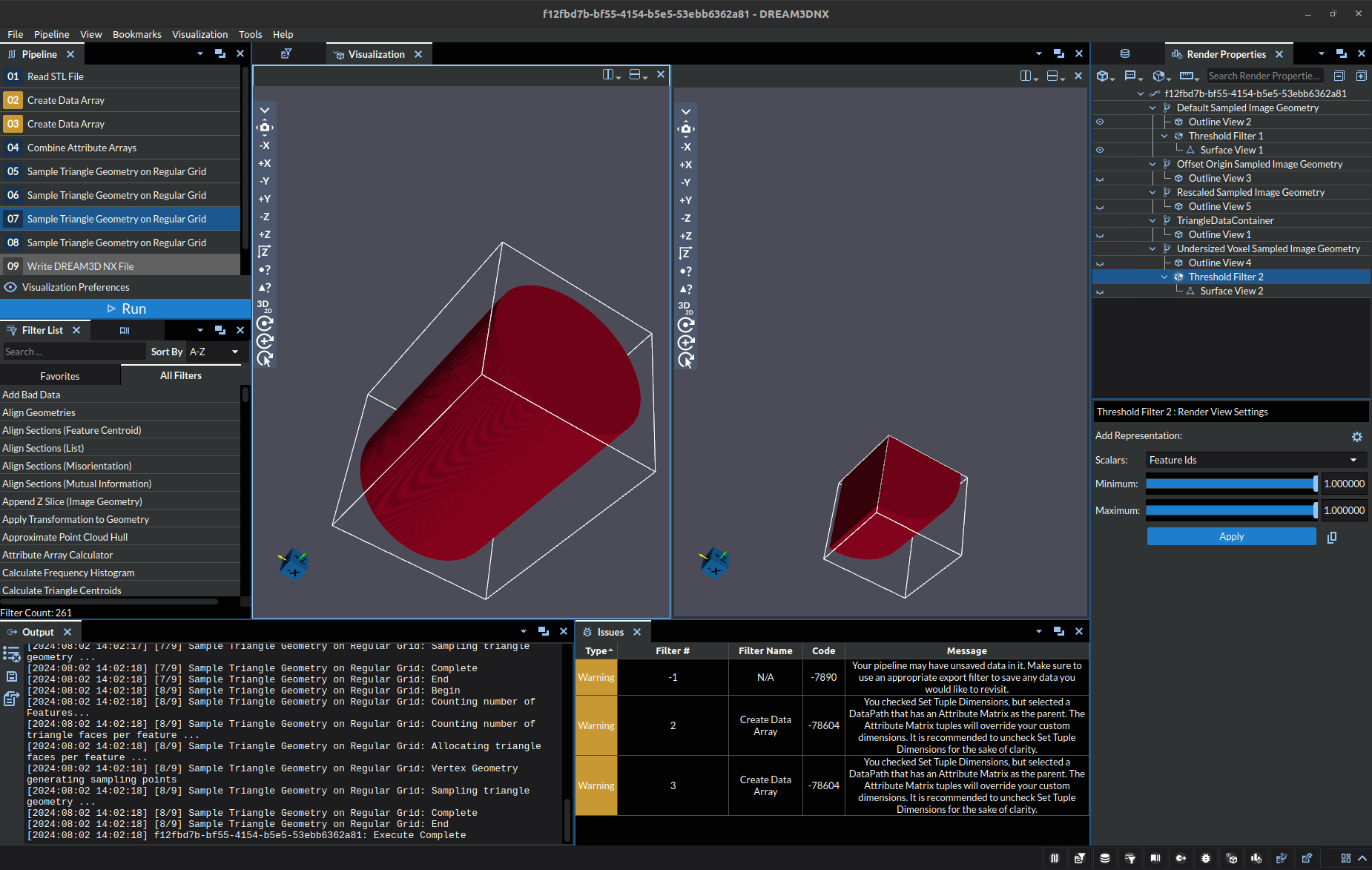
In the above picture, the cylinder on the left is a correct output for a specific .stl model, the dimensions used was (440, 440, 640). On the right, there is a cylinder that had the dimensions set to (240, 240, 240). The change in dimensions led to a large truncation of the overall geometry. This parameter is the most difficult to fine tune since setting the dimensions too large can easily blow out your RAM needlessly, while too small will truncate sections potentially leading to output looking deformed (such as a rectangle appearing as a square).
Scaling
Take a moment to consider the following image:
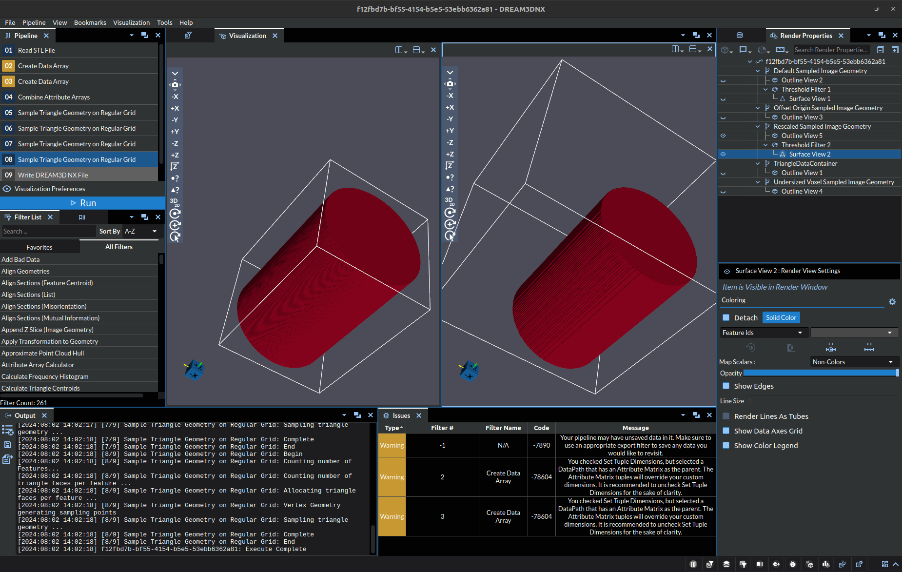
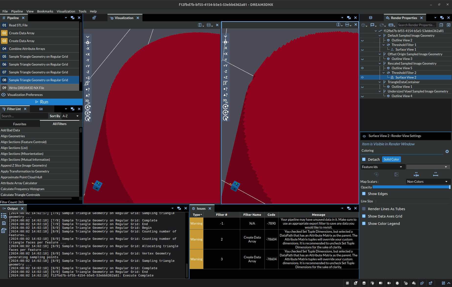
In the above picture, the cylinder on the left is a correct output for a specific .stl model, the scaling used was (0.05, 0.05, 0.05) with dimensions of (440, 440, 640). On the right, there is a cylinder that had the scaling set to (0.15, 0.15, 0.15) with dimensions of (240, 240, 240). You will notice there is no truncation to the geometry despite the smaller box dimensions, thus scaling can be used to reduce the size of the data. However, there is a caveat, less points means less detail. The astute may have noticed the cylinder on the right looks more “pixelated” despite having no truncation. Here’s a close up image of the edge for easier viewing:
Tips
It’s easiest to think about these parameters as if you were defining a 3D image to capture. The Dimensions are the pixels (voxels) in your image. They allow you to define the detail (resolution) of the resulting image:
lower values will save space and run faster, but be pixelated
higher values will be detailed, but consume more space and take longer to process.
The spacing allows you to scale the size of the bounding box, which can be thought of as similar to zooming a camera in/out from your focal point.
larger scaling values can make the capture (bounding box/grid) too large, and your focal point will become pixelated because its “too small” in the overall image. Think about zooming in super close to a picture.
smaller scaling values are bring the focal point closer, ensuring more detail is captured. However, if you get too close pieces of the focal point will be missing from the image, but what you do capture will have lots of detail.
The origin can be thought of as moving the camera left and right and up and down. Allowing you to center the focal point in the image or cut out unwanted parts.
All in all, it is best practice to try to fit the bounding box as closely to the actual geometry as possible to ensure you get the most detail out of the used memory.
Input Parameter(s)
Parameter Name |
Parameter Type |
Parameter Notes |
Description |
|---|---|---|---|
Use existing geometry |
Choices |
Should the filter create a new geometry or use an existing one |
|
Dimensions (Voxels) |
Vector of UInt64 Values |
Order=x,y,z |
The dimensions of the created Image geometry |
Origin |
Vector of Float32 Values |
Order=x,y,z |
The origin of the created Image geometry |
Spacing |
Vector of Float32 Values |
Order=x,y,z |
The spacing of the created Image geometry |
Length Units (For Description Only) |
Choices |
The units to be displayed below |
Input Data Objects
Parameter Name |
Parameter Type |
Parameter Notes |
Description |
|---|---|---|---|
Triangle Geometry |
Geometry Selection |
Triangle |
The geometry to be sampled onto grid |
Face Labels/Part Numbers |
Array Selection |
Allowed Types: int8, uint8, int16, uint16, int32, uint32, int64, uint64 Comp. Shape: 12 |
Array specifying which Features are on either side of each Face. Accepts 1-component (single part number per face) or 2-component arrays. |
Image Geometry |
Geometry Selection |
Image |
The path to the existing image geometry to use |
Output Image Geometry
Parameter Name |
Parameter Type |
Parameter Notes |
Description |
|---|---|---|---|
Image Geometry |
DataGroupCreation |
The name and path for the image geometry to be created |
Output Cell Attribute Matrix
Parameter Name |
Parameter Type |
Parameter Notes |
Description |
|---|---|---|---|
Cell Attribute Matrix |
DataObjectName |
The name for the cell data Attribute Matrix within the Image geometry |
Output Cell Data
Parameter Name |
Parameter Type |
Parameter Notes |
Description |
|---|---|---|---|
Feature Ids |
DataObjectName |
The name for the feature ids array in cell data Attribute Matrix |
License & Copyright
Please see the description file distributed with this Plugin
DREAM3D-NX Help
If you need help, need to file a bug report or want to request a new feature, please head over to the DREAM3DNX-Issues GitHub site where the community of DREAM3D-NX users can help answer your questions.