12.50. Segment Features (Misorientation)
Group (Subgroup)
Reconstruction (Segmentation)
Description
This Filter groups neighboring Cells (voxels) that have similar crystal orientations into Features (grains), producing a FeatureIds array that labels every cell in the input Image Geometry with a grain number. This is the primary grain-segmentation filter for EBSD data and is usually the first feature-generating step in a reconstruction pipeline.
For segmentation based only on C-axis alignment in hexagonal materials, see Segment Features (C-Axis Misalignment). For segmentation based on a scalar value rather than orientation, see Segment Features (Scalar).
What is Misorientation-Based Segmentation?
A grain in a polycrystalline material is a region of crystal with a nearly-uniform lattice orientation. At grain boundaries the lattice rotates abruptly – typically by many degrees – from one grain to the next. Within a grain, orientation changes are small (sub-degree to a few degrees), due to noise, elastic strain, or mild plastic deformation.
Misorientation is the angular rotation that maps one crystal orientation onto another. By walking cell-to-cell and merging neighbors whose misorientation is below a threshold, this filter carves the cell-level orientation map into discrete grains.
How This Filter Works
The filter uses a standard burn algorithm to grow each grain outward from a seed cell:
Randomly pick an unassigned Cell and give it a new Feature Id.
Compute the misorientation angle between the seed cell and each neighbor (see Neighbor Scheme below). Crystal symmetry is applied so that the smallest symmetry-equivalent angle is used.
Any neighbor whose misorientation angle is less than the user-specified Misorientation Tolerance (in degrees) is added to the current feature and gets the same Feature Id.
Repeat step 2-3 from each newly added cell, growing the feature outward until no more neighbors qualify.
Increment the feature counter and pick a new unassigned seed cell. Continue until every eligible cell has been assigned.
Example: Before and After
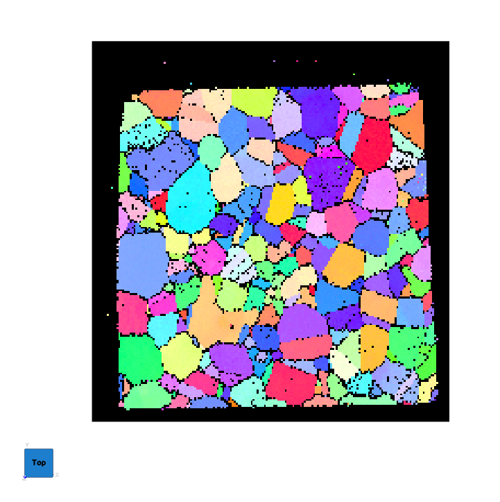
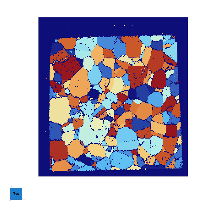
The single EBSD slice below is shown first as an IPF (inverse pole figure) color map of the raw cell orientations, then after misorientation-based segmentation, where each grain has been assigned a distinct Feature Id and colored categorically.
IPF Color Map (input orientations) |
Segmented Grains (Feature Ids) |
|---|---|
|
|
Typical Tolerance Values
The Misorientation Tolerance is in degrees. The right value depends on what you are trying to resolve:
5 degrees – the industry-standard default for general grain segmentation. Works well across most materials.
2-3 degrees – tighter; useful when the data is very clean and you want to resolve subgrains or low-angle boundaries.
10-15 degrees – the classical “high-angle grain boundary” threshold. Useful if you want to ignore subgrain structure entirely and segment only the high-angle grains.
Smaller tolerances produce more, smaller features and will pick up noise and subgrain boundaries as feature splits. Larger tolerances produce fewer, larger features at the cost of possibly merging neighboring grains that have a low-angle boundary between them.
Phase Handling
Only cells belonging to the same phase are ever merged. Cells of different phases are always considered different features regardless of their orientation, because misorientation between different crystal systems is not physically meaningful. Cells with phase = 0 (the “Unknown” phase) are treated as unsegmentable and receive Feature Id 0.
Neighbor Scheme
The Neighbor Scheme parameter provides the following choices:
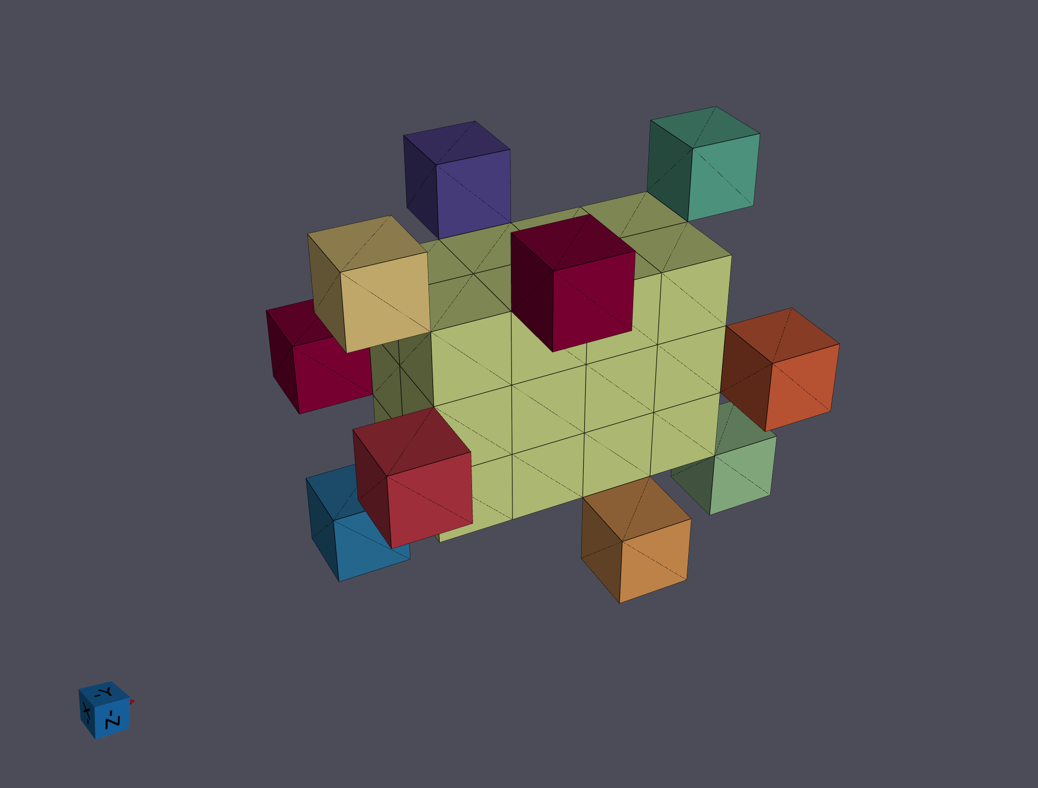
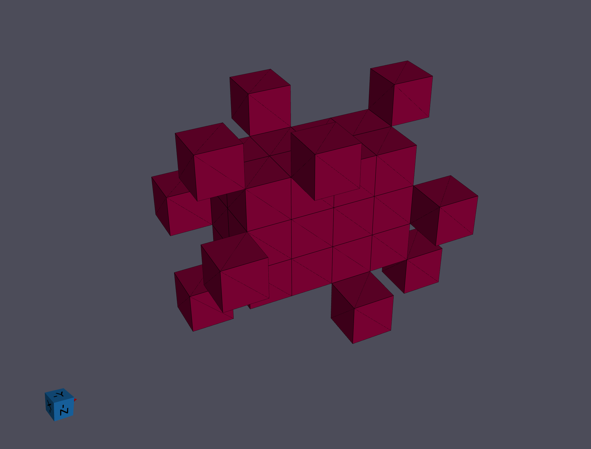
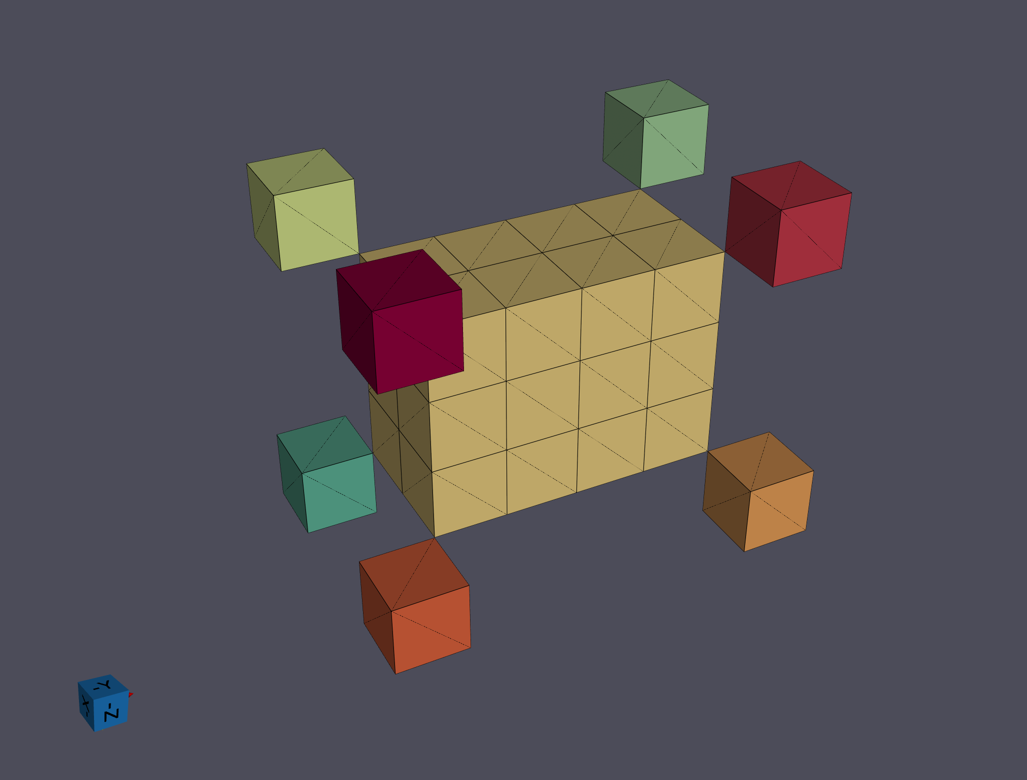
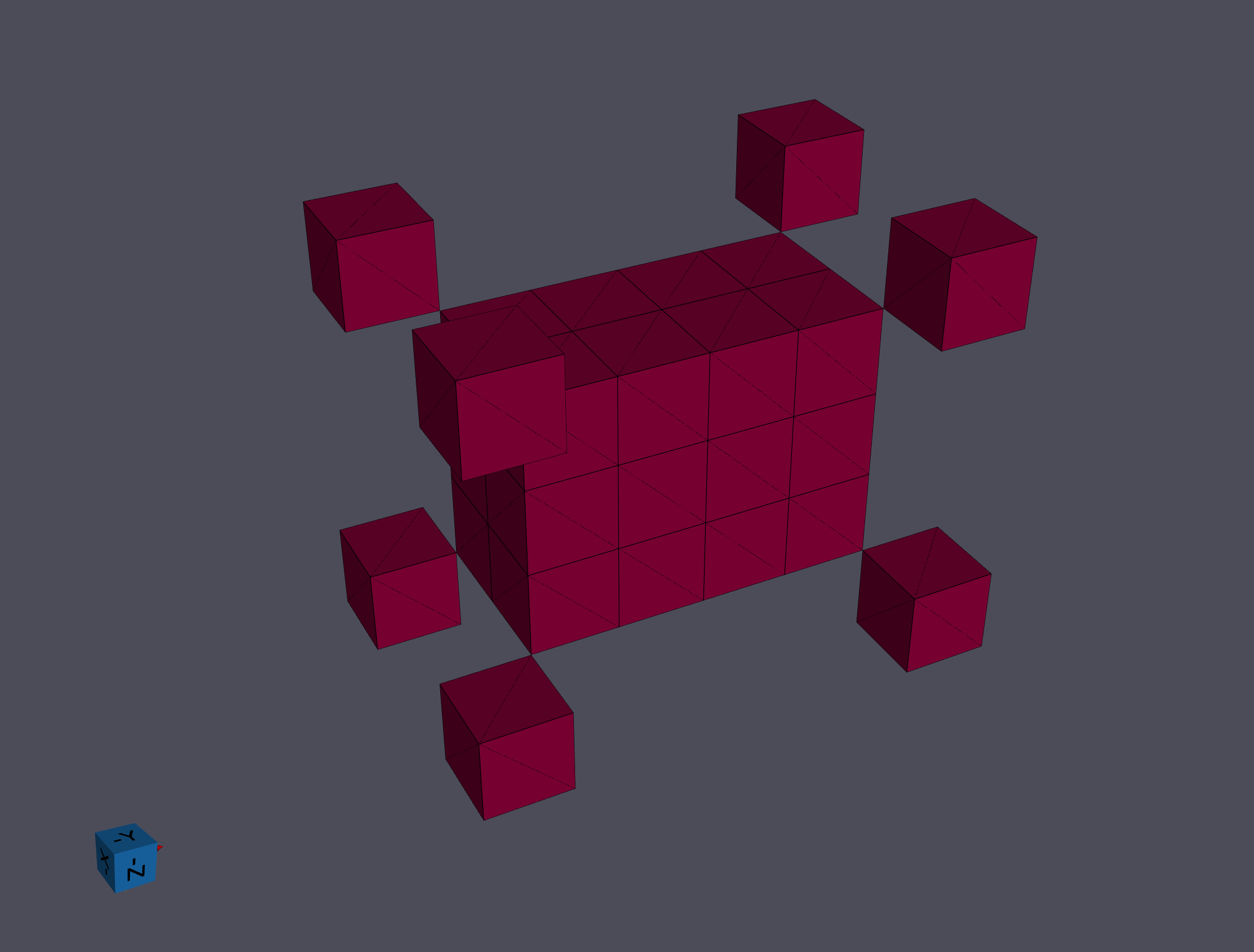
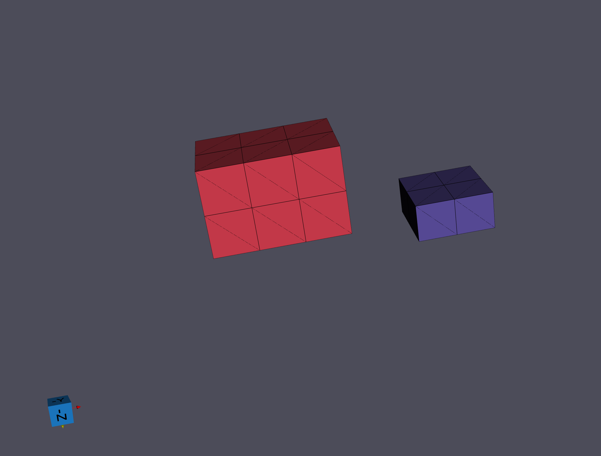
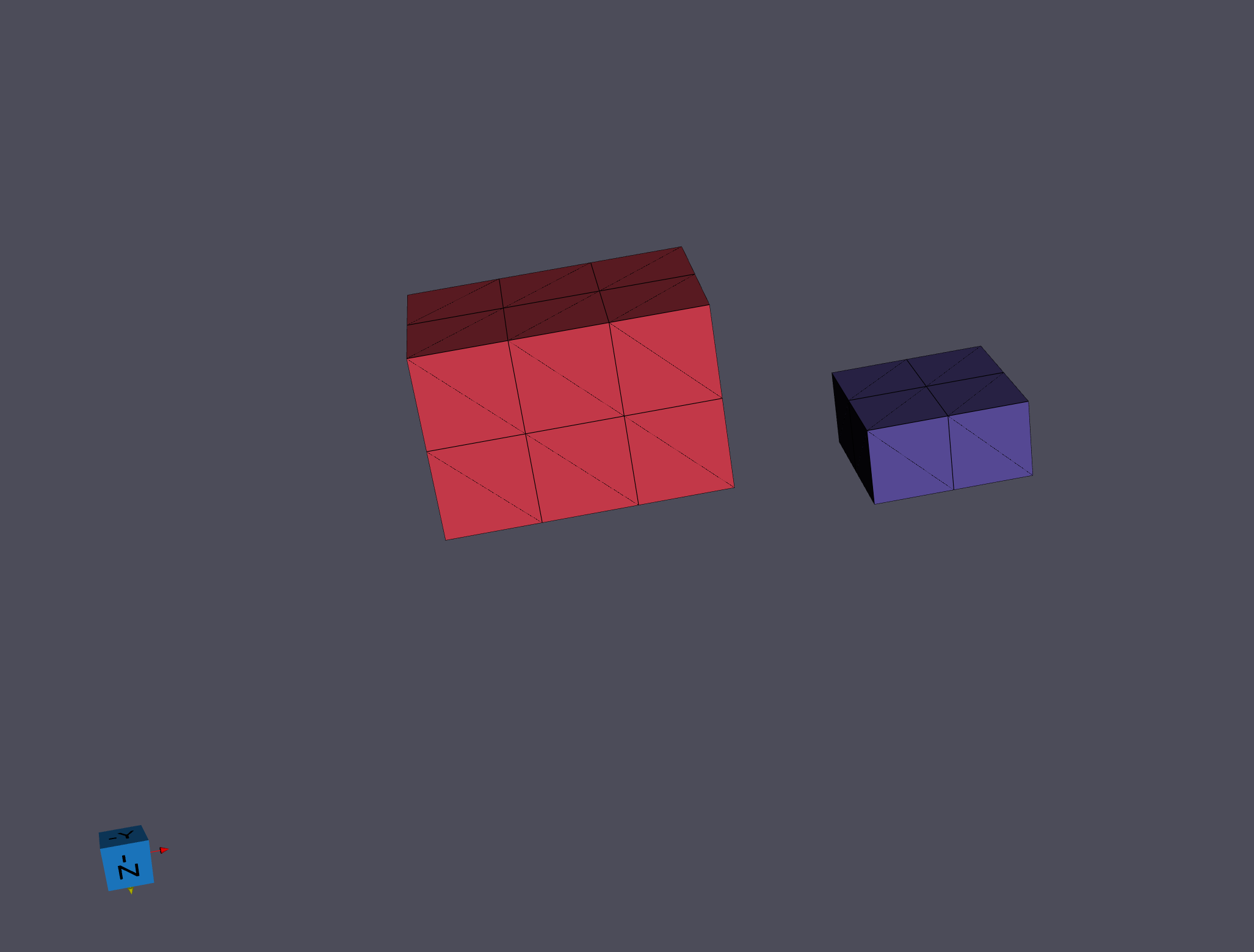
Face Neighbors [0]: Only the 6 face-sharing neighbors of a voxel are considered during segmentation.
All Connected Neighbors [1]: All 26 neighbors connected by a face, edge, or vertex are considered during segmentation.
DREAM.3D version 6.x only used face neighbors. The default here is still Face Only for backward compatibility; switch to All Connected when diagonal connectivity should merge a grain that would otherwise be split into two features.
Neighbor Scheme = “Face Only” |
Neighbor Scheme = “All Connected” |
|---|---|
|
|
Neighbor Scheme = “Face Only” |
Neighbor Scheme = “All Connected” |
|---|---|
|
|
Neighbor Scheme = “Face Only” |
Neighbor Scheme = “All Connected” |
|---|---|
|
|
Neighbor Scheme = “Face Only” |
Neighbor Scheme = “All Connected” |
|---|---|
|
|
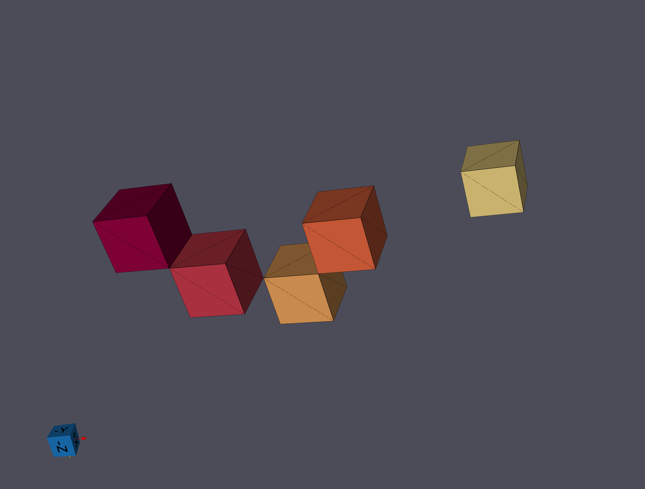
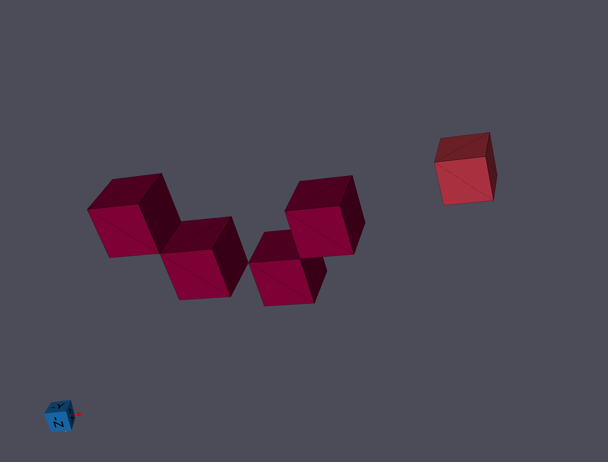
Mask Array
If Use Mask Array is enabled, cells flagged false in the mask are excluded from segmentation and left with a Feature Id of 0. This is essential for EBSD data where low-confidence cells should not be merged into grains – typically use a threshold on the confidence index or image quality to build the mask via Multi-Threshold Objects.
Periodic Option
If the input data represents a periodic volume (e.g., a synthetic microstructure that tiles across opposite faces), enable Is Periodic. The filter will detect features that wrap across the geometry bounds and emit a warning that centroid and other spatial statistics may be incorrect for those features.
Required Input Sources
Cell Quaternions – typically read from EBSD data via Read H5EBSD, Read CTF Data, or Read ANG Data; can also be produced from Euler angles by Convert Orientations.
Cell Phases – typically read from EBSD data alongside the quaternions.
Crystal Structures – ensemble-level array read from EBSD data or created by Create Ensemble Info.
Mask Array (optional) – a boolean array marking valid cells, typically produced by Multi-Threshold Objects.
Input Parameter(s)
Parameter Name |
Parameter Type |
Parameter Notes |
Description |
|---|---|---|---|
Misorientation Tolerance (Degrees) |
Scalar Value |
Float32 |
Tolerance (in degrees) used to determine if neighboring Cells belong to the same Feature |
Randomize Feature Ids |
Bool |
Specifies if feature IDs should be randomized during calculations |
|
Neighbor Scheme |
Choices |
How many neighbors to use |
Optional Data Mask
Parameter Name |
Parameter Type |
Parameter Notes |
Description |
|---|---|---|---|
Use Mask Array |
Bool |
Specifies whether to use a boolean array to exclude some Cells from the Feature identification process |
|
Cell Mask Array |
Array Selection |
Allowed Types: uint8, boolean Comp. Shape: 1 |
Path to the data array that specifies if the Cell is to be counted in the algorithm |
Input Cell Data
Parameter Name |
Parameter Type |
Parameter Notes |
Description |
|---|---|---|---|
Input Grid Geometry |
Geometry Selection |
Image, Rectilinear Grid |
DataPath to input Grid Geometry |
Cell Quaternions |
Array Selection |
Allowed Types: float32 Comp. Shape: 4 |
Specifies the orientation of the Cell in quaternion representation |
Cell Phases |
Array Selection |
Allowed Types: int32 Comp. Shape: 1 |
Specifies to which Ensemble each cell belongs |
Input Ensemble Data
Parameter Name |
Parameter Type |
Parameter Notes |
Description |
|---|---|---|---|
Crystal Structures |
Array Selection |
Allowed Types: uint32 Comp. Shape: 1 |
Enumeration representing the crystal structure for each Ensemble |
Output Cell Data
Parameter Name |
Parameter Type |
Parameter Notes |
Description |
|---|---|---|---|
Cell Feature Ids |
DataObjectName |
Specifies to which feature each cell belongs. |
Output Feature Data
Parameter Name |
Parameter Type |
Parameter Notes |
Description |
|---|---|---|---|
Feature Attribute Matrix |
DataObjectName |
The name of the created cell feature attribute matrix |
|
Active |
DataObjectName |
The name of the array which specifies if the Feature is still in the sample (true if the Feature is in the sample and false if it is not). At the end of the Filter, all Features will be Active |
|
Is Periodic |
Bool |
Should segment features wrap around the image data |
Example Pipelines
(02) Small IN100 Full Reconstruction
INL Export
04_Steiner Compact
License & Copyright
Please see the description file distributed with this Plugin
DREAM3D-NX Help
If you need help, need to file a bug report or want to request a new feature, please head over to the DREAM3DNX-Issues GitHub site where the community of DREAM3D-NX users can help answer your questions.