11.44. Read Oxford Instr. Channel 5 (.cpr/.crc)
Group (Subgroup)
IO (Input)
Description
This filter will read a single .cpr/.crc file pair into a new ImageGeometry. A Cell Attribute Matrix and Ensemble Attribute Matrix** will also be created to hold the imported EBSD information. Currently, the user has no control over the names of the created Attribute Arrays. The user should be aware that simply reading the file then performing operations that are dependent on the proper crystallographic and sample reference frame will be undefined, inaccurate and/or wrong. In order to bring the crystal reference frame and sample reference frame into coincidence, rotations will need to be applied to the data. An excellent reference for this is the following PDF file: http://pajarito.materials.cmu.edu/rollett/27750/L17-EBSD-analysis-31Mar16.pdf
Default HKL Transformations
If the data has come from a HKL acquisition system and the settings of the acquisition software were in the default modes, then the following reference frame transformations need to be performed:
Sample Reference Frame: 180o about the <010> Axis
Crystal Reference Frame: None
The user also may want to assign un-indexed pixels to be ignored by flagging them as “bad”. The Threshold Objects Filter can be used to define this mask by thresholding on values such as Error = 0. This will mark all scan points that have Error=0 as TRUE, which means those scan points are valid for processing.
Radians and Degrees
2D .cpr/.crc files have their angles in radians.
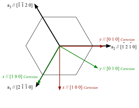
The Axis Alignment Issue for Hexagonal Symmetry [1]
The issue with hexagonal materials is the alignment of the Cartesian coordinate system used for calculations with the crystal coordinate system (the Bravais lattice).
In one convention (e.g. EDAX.TSL), the x-axis, i.e. [1,0,0], is aligned with the crystal a1 axis, i.e. the [2,-1,-1,0] direction. In this case, the y-axis is aligned with the [0,1,-1,0] direction. (Green Axis in Figure 1)
In the other convention, (e.g. Oxford Instr, Univ. Metz software), the x-axis, i.e. [1,0,0], is aligned with the crystal [1,0,-1,0] direction. In this case, the y-axis is aligned with the [-1,2,-1,0] direction. (Red Axis in Figure 1)
This is important because texture analysis can lead to an ambiguity as to the alignment of [2,-1,-1,0] versus [1,0,-1,0], with apparent 30 Degree shifts in the data.
Caution: it appears that the axis alignment is a choice that must be made when installing TSL software so determination of which convention is in use must be made on a case-by-case basis. It is fixed to the y-convention in the HKL software.
The main clue that something is wrong in a conversion is that either the 2110 & 1010 pole figures are transposed, or that a peak in the inverse pole figure that should be present at 2110 has shifted over to 1010.
DREAM3D-NX uses the TSL/EDAX convention.
The result of this is that the filter will by default add 30 degrees to the second Euler Angle (phi2) when reading Oxford Instr (.ctf) files. This can be disabled by the user if necessary.
Figure 1 |
|---|
|
Figure 1:showing TSL and Oxford Instr. conventions. EDAX/TSL is in Green. Oxford Inst. is inRed |
Input Parameter(s)
Parameter Name |
Parameter Type |
Parameter Notes |
Description |
|---|---|---|---|
Input File (.cpr) |
FileSystemPath |
The input .cpr file path. The .crc file must also exist. |
|
Convert Hexagonal X-Axis to EDAX Standard |
Bool |
Whether or not to convert a Hexagonal phase to the EDAX standard for x-axis alignment |
|
Convert Data Arrays to be more compatible with DREAM3D |
Bool |
Some arrays will be converted from the type they are in the file to more compatible types. |
Output Image Geometry
Parameter Name |
Parameter Type |
Parameter Notes |
Description |
|---|---|---|---|
Image Geometry |
DataGroupCreation |
The path to the created Image Geometry |
Output Cell Attribute Matrix
Parameter Name |
Parameter Type |
Parameter Notes |
Description |
|---|---|---|---|
Cell Attribute Matrix |
DataObjectName |
The name of the cell data attribute matrix for the created Image Geometry |
Output Ensemble Attribute Matrix
Parameter Name |
Parameter Type |
Parameter Notes |
Description |
|---|---|---|---|
Ensemble Attribute Matrix |
DataObjectName |
The Attribute Matrix where the phase information is stored. |
Example Pipelines
License & Copyright
Please see the description file distributed with this Plugin
References
[1] Rollett, A.D. Lecture Slides located at http://pajarito.materials.cmu.edu/rollett/27750/L17-EBSD-analysis-31Mar16.pdf
DREAM3D-NX Help
If you need help, need to file a bug report or want to request a new feature, please head over to the DREAM3DNX-Issues GitHub site where the community of DREAM3D-NX users can help answer your questions.