12.46. Read Oxford Instr. EBSD Data (.ctf)
Group (Subgroup)
IO (Input)
Description
This filter reads a single .ctf file (the EBSD scan format written by Oxford Instruments / HKL Channel 5 software) into a new Image Geometry. Reading the file directly lets the data be used immediately by other filters, instead of having to first build an intermediate .h5ebsd file. A Cell Attribute Matrix (per-pixel data) and an Ensemble Attribute Matrix (per-phase data) are created to hold the imported EBSD information. The user currently has no control over the names of the created Attribute Arrays.
The scan stores an orientation at every pixel as three Euler angles (three angles, in the Bunge Z-X-Z convention, describing how the measured crystal at that pixel is rotated relative to the sample).
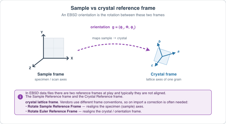
The user should be aware that simply reading the file and then performing operations that depend on a correct crystal reference frame (the axes fixed to the crystal lattice) and sample reference frame (the axes fixed to the physical specimen) will be undefined, inaccurate and/or wrong. To bring the crystal and sample reference frames into coincidence, rotations may need to be applied to the data. An excellent reference for this is the following PDF file: http://pajarito.materials.cmu.edu/rollett/27750/L17-EBSD-analysis-31Mar16.pdf
Multi-Slice (3D) .ctf Files
If the file header declares more than one slice (ZCells > 1), the created Image Geometry is sized X × Y × Z and the slice thickness is taken from the header’s ZStep key (a missing or zero ZStep defaults to 1.0). Single-slice (2D) files produce a geometry with a z-extent of 1.
Unindexed Points (Phase 0)
Points the acquisition software could not index (“zero solutions”) carry a phase value of 0 in the .ctf file, and this filter preserves that value in the Phases array. (Legacy DREAM3D 6.5 remapped these points to phase 1, silently assigning them to a real phase — see the migration notes below.) To mask unindexed points, threshold on Error = 0 (see below) or on Phases > 0.
Default HKL Transformations
If the data has come from a HKL acquisition system and the settings of the acquisition software were in the default modes, then the following reference frame transformations need to be performed. These rotations can be applied with Rotate Sample Reference Frame and Rotate Euler Reference Frame:
Sample Reference Frame: 180o about the <010> Axis
Crystal Reference Frame: None
The user also may want to assign un-indexed pixels to be ignored by flagging them as “bad”. The Multi-Threshold Objects filter can be used to define this mask by thresholding on values such as Error = 0.
Memory Requirements
While the filter executes, the reader’s per-column buffers and the created Attribute Arrays are resident simultaneously: peak memory is roughly 88 bytes per scan point for a standard 11-column file (about 4.4 GB for a 50-million-point map). Files carrying optional columns (Z, GrainIndex, GrainRandomColour) cost about 4 bytes per point more for each extra column.
Radians and Degrees
Most 2D .ctf files store their angles in degrees, whereas DREAM3D-NX expects radians. The filter provides an option to convert the Euler angles to radians, turned on by default. The user is encouraged to create an IPF (Inverse Pole Figure) image of their EBSD data to confirm whether this option actually needs to be enabled.
Downstream Processing
Once the reference frames are correct, the imported Euler angles are typically converted to other orientation representations (quaternions, and so on) with Convert Orientation Representation before computing misorientations, segmenting grains, or generating pole figures.
Required Input Sources
None — this filter reads directly from a .ctf file on disk.
The Axis Alignment Issue for Hexagonal Symmetry (Advanced) [1]
The issue with hexagonal materials is the alignment of the Cartesian coordinate system used for calculations with the crystal coordinate system (the Bravais lattice).
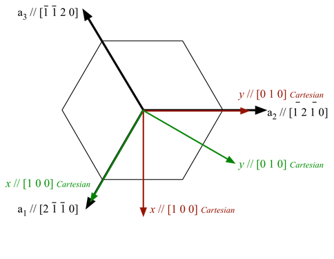
In one convention (e.g. EDAX.TSL), the x-axis, i.e. [1,0,0], is aligned with the crystal a1 axis, i.e. the [2,-1,-1,0] direction. In this case, the y-axis is aligned with the [0,1,-1,0] direction. (Green Axis in Figure 1)
In the other convention, (e.g. Oxford Instr, Univ. Metz software), the x-axis, i.e. [1,0,0], is aligned with the crystal [1,0,-1,0] direction. In this case, the y-axis is aligned with the [-1,2,-1,0] direction. (Red Axis in Figure 1)
This is important because texture analysis can lead to an ambiguity as to the alignment of [2,-1,-1,0] versus [1,0,-1,0], with apparent 30 Degree shifts in the data.
Caution: it appears that the axis alignment is a choice that must be made when installing TSL software so determination of which convention is in use must be made on a case-by-case basis. It is fixed to the y-convention in the HKL software.
The main clue that something is wrong in a conversion is that either the 2110 & 1010 pole figures are transposed, or that a peak in the inverse pole figure that should be present at 2110 has shifted over to 1010.
DREAM3D-NX uses the TSL/EDAX convention.
The result of this is that the filter will by default add 30 degrees to the third Euler angle (phi2) of every point belonging to a hexagonal (6/mmm) phase when reading Oxford Instr (.ctf) files. Unindexed (Phase 0) points are never shifted. This can be disabled by the user if necessary.
Figure 1 |
|---|
|
Figure 1: showing TSL and Oxford Instr. conventions. EDAX/TSL is in Green. Oxford Instr. is in Red. |
Input Parameter(s)
Parameter Name |
Parameter Type |
Parameter Notes |
Description |
|---|---|---|---|
Input File |
FileSystemPath |
The input .ctf file path |
|
Convert Euler Angles to Radians |
Bool |
Whether or not to convert the Euler angles to Radians |
|
Convert Hexagonal X-Axis to EDAX Standard |
Bool |
Whether or not to convert a Hexagonal phase to the EDAX standard for x-axis alignment |
Output Image Geometry
Parameter Name |
Parameter Type |
Parameter Notes |
Description |
|---|---|---|---|
Image Geometry |
DataGroupCreation |
The path to the created Image Geometry |
Output Cell Attribute Matrix
Parameter Name |
Parameter Type |
Parameter Notes |
Description |
|---|---|---|---|
Cell Attribute Matrix |
DataObjectName |
The name of the cell data attribute matrix for the created Image Geometry |
Output Ensemble Attribute Matrix
Parameter Name |
Parameter Type |
Parameter Notes |
Description |
|---|---|---|---|
Ensemble Attribute Matrix |
DataObjectName |
The Attribute Matrix where the phase information is stored. |
Migration Notes from DREAM3D 6.5
Documented behavioral differences from legacy DREAM3D 6.5 are maintained as Deviation entries in the source tree at src/Plugins/OrientationAnalysis/vv/deviations/ReadCtfDataFilter.md. In brief: unindexed points keep their phase value of 0 (legacy remapped them to 1, and consequently also applied the hexagonal +30° shift to them), and malformed .ctf files that crashed legacy DREAM3D are rejected with descriptive errors.
Example Pipelines
TxCopper_Exposed
TxCopper_Unexposed
License & Copyright
Please see the description file distributed with this Plugin
References
[1] Rollett, A.D. Lecture Slides located at http://pajarito.materials.cmu.edu/rollett/27750/L17-EBSD-analysis-31Mar16.pdf
DREAM3D-NX Help
If you need help, need to file a bug report or want to request a new feature, please head over to the DREAM3DNX-Issues GitHub site where the community of DREAM3D-NX users can help answer your questions.